What Will I Learn?
In this tutorial, reader :
- will learn how to use probes in SimulIDE
- will learn changing properties in SimulIDE
- how to extracting codes and use them in SimulIDE

Requirements
To complete the tutorial, utopians would have
- basic knowledge about circuits
- SimulIDE circuit simulator software
- basic knowledge how to use SimulIDE circuit simulator software
Difficulty
- Basic
Tutorial Contents
In this tutorial, I am going to describe some properties of SimulIDE circuit simulator that users need to know. By knowing those properties, users will be able to construct satisfied number of circuits.
I will start with usage of probes, then move to how to change properties, and use them and lastly, how to extract the code and share your circuit to other users. Apart from other tutorials, this one will focus on main parts of the software not to focus particular examples. Lets start one by one.
- Episode 1: Usage of probes
As an engineers, we know that probes are vital elements for us. They enlighten the information behind the circuits, and they are must be used in simulator softwares. In this part, I will talk about them. To reach the probes, user should find "Probe" under "Meters" in component parts as shown below.
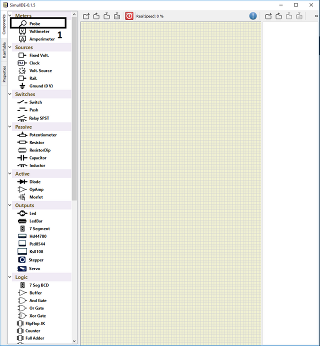
They are basically to used to measure the current and voltage. I have constructed a simple RC circuit to show.
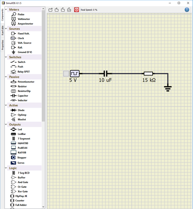
And I have placed the probes as I have indicated above, after that started simulation
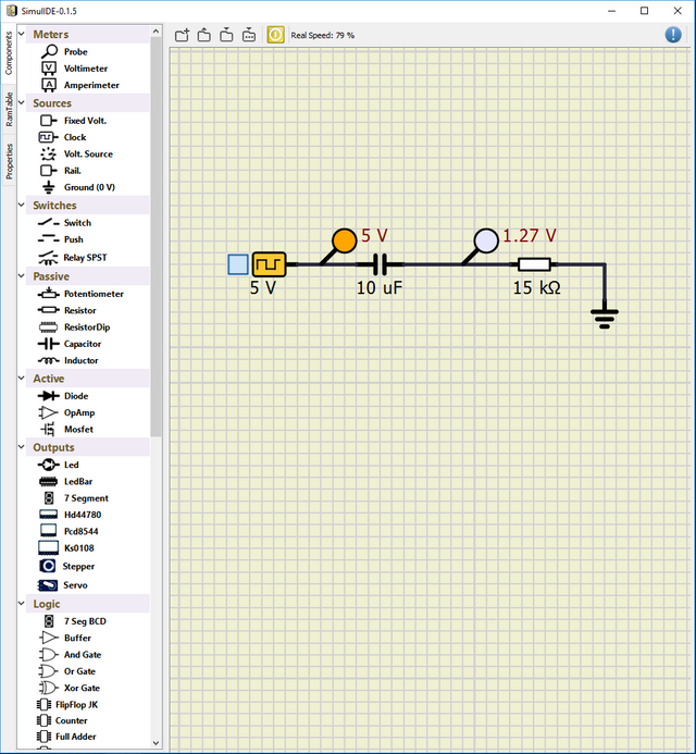
When you right click to the probes and click to "add to plotter", you will be able to see scope graphs at the bottom of the software.
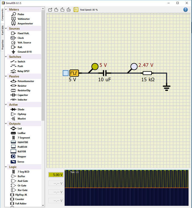
If you want to add more than one scope to bottom, you need to click desired scope and do same operation indicated above. When both of them are activated, circuit looks like:
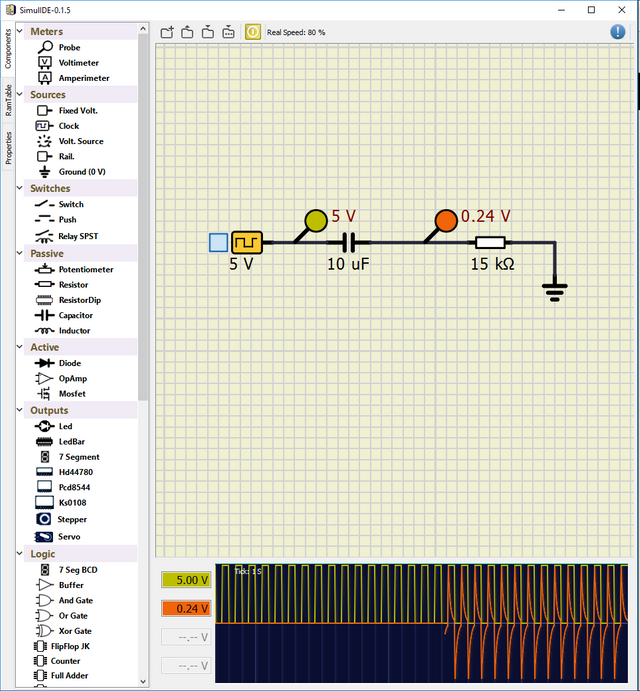
This is the fundamental logic behind the "Probe" property of the software.
- Episode 2: Changing the properties of the components
In this part, I will try to explain how to change the properties for components which are used for the circuit. First stage is to right click to the desired component and click to properties as shown below:
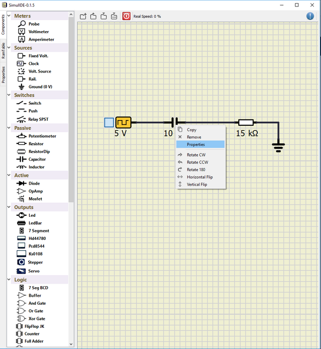
At the left window, new frame appears and user can change the parameters. You may need to change the capacitances,resistances,frequency of the sources, and many more. One example is that, I have talked about logic gates in my past tutorials. In [part 1]https://utopian.io/utopian-io/@escorn/electronics-simulations-2-or-illustration-of-2-bit-comparator-by-using-simulide-simulator) and part 2, I have used logic gates, which is not stated in the component list and more than 2 inputs. For those cases, we can simply use properties function of the software such that, we can take an AND gate and change its parameters as we wish
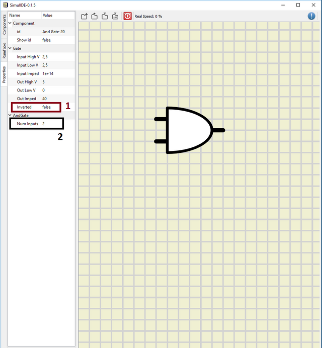
From 1, user can change the output as inverted or not. You can change an AND gate to a NAND gate by this property, and from 2, user can change number of inputs, I have changed number of inputs to 4 and inverted it, as a result I have 4 input NAND gate as shown below:
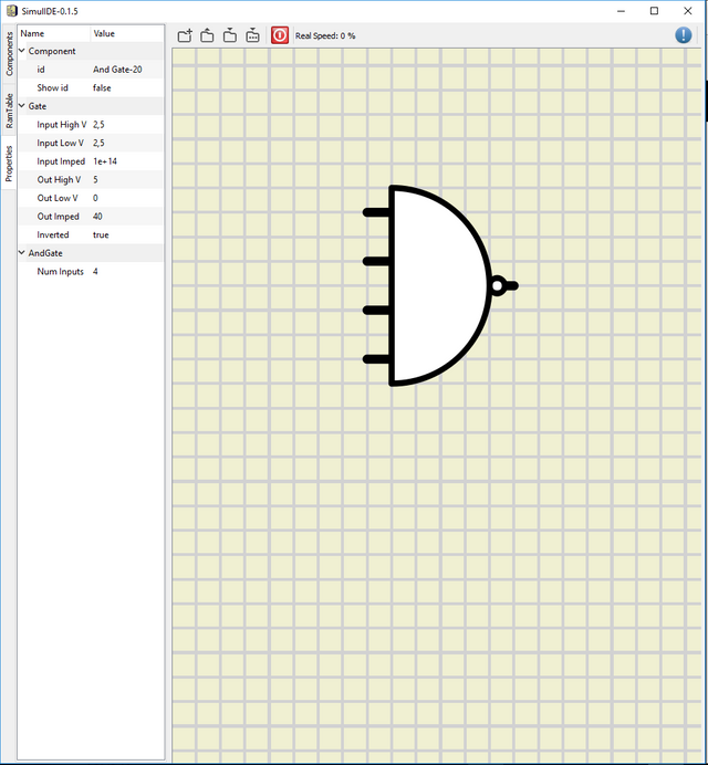
You can change any parameter in any component as you wish by using properties function.
- Episode 3: Extracting circuit as codes and use them
As a last part, I will show how to extract circuit as codes and how to use them in the software. SimulIDE has a great property such that, you can save your circuit as codes and use them whenever and wherever you want. First step you need to do is save the circuit by using the top bar.
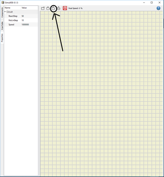
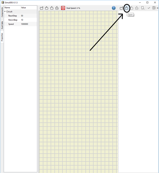
You will save your file as .simu file in desired location. After you close the software and want to re use your saved circuit, you need to drag right bar and click the button.
When you click and select your desired circuit, the saved circuit will appear as codes. To show that I have used the circuit that I have constructed in part 2 . You can compile and debug your code in that part, and I have loaded my circuit to main window too. The result looks like:
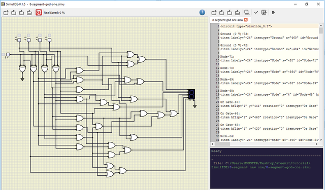
This tool is really strong and helps designer to find the bugs & errors in the circuit.
If you have any questions, please feel free to ask me on Discord (Escorn#4114)
Curriculum
I have provided the previous tutorials that I have prepared for the community:
Posted on Utopian.io - Rewarding Open Source Contributors
@escorn, Upvote is the only thing I can support you.
Downvoting a post can decrease pending rewards and make it less visible. Common reasons:
Submit
Thank you for the contribution. It has been approved.
You can contact us on Discord.
[utopian-moderator]
Downvoting a post can decrease pending rewards and make it less visible. Common reasons:
Submit
Hey @escorn I am @utopian-io. I have just upvoted you!
Achievements
Suggestions
Get Noticed!
Community-Driven Witness!
I am the first and only Steem Community-Driven Witness. Participate on Discord. Lets GROW TOGETHER!
Up-vote this comment to grow my power and help Open Source contributions like this one. Want to chat? Join me on Discord https://discord.gg/Pc8HG9x
Downvoting a post can decrease pending rewards and make it less visible. Common reasons:
Submit