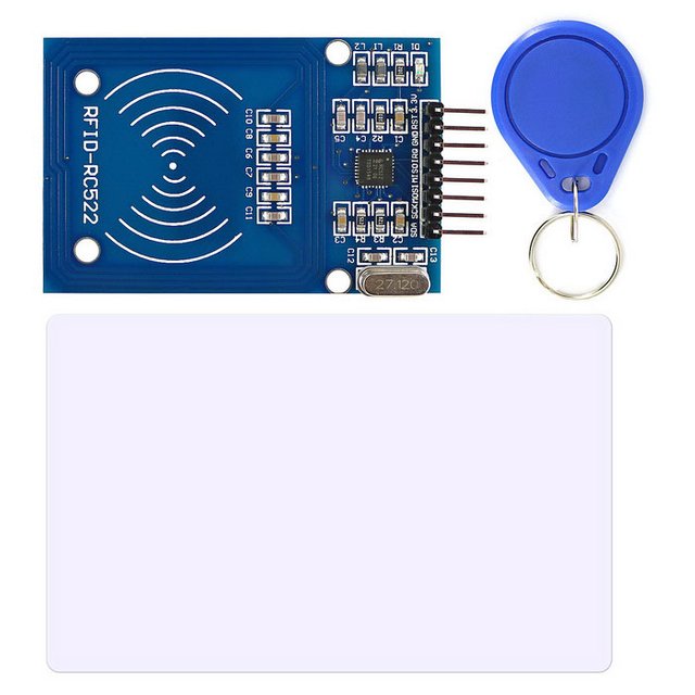
Radio-Frequency Identification (RFID) uses electromagnetic fields to automatically identify and track tags attached to objects. These tags contain electronically stored information. Different tags are usually attached to objects and when we place that object in front of the reader, the reader reads the tags. Another benefit of RFID is that it doesn’t require to be in a line of sight to get detected. In this tutorial, I used MF RC522 that can detect tags up to 15cm. And this tutorial aims to light up an LED when the right tag will be detected.
What Will I Learn?
- How to interface RC522 RFID Scanner with Arduino
- Light up LED using the RC522 RFID Scanner
Requirements
- Arduino Uno
- MF RC522 RFID Scanner
- Connecting Wires
- LED
- 330 ohms resistor
- Breadboard
Difficulty
- Basic
Tutorial Contents
Step 1: Physical Connection from RC522 RFID Scanner to Arduino Uno

Created using fritzing
Connect the following:
| RFID Scanner | Arduino Uno |
|---|---|
| SDA | pin 10 |
| SCK | pin 13 |
| MOSI | pin 11 |
| MISO | pin 12 |
| GND | GND |
| RST | pin 8 |
| 3.3V | 3.3V |
- pin 4 to resistor and the resistor connected to the (+ sign) of LED then the (- sign) to the GND.
Step 2: Software Connection
- Connect the USB Cable to a PC/Laptop.
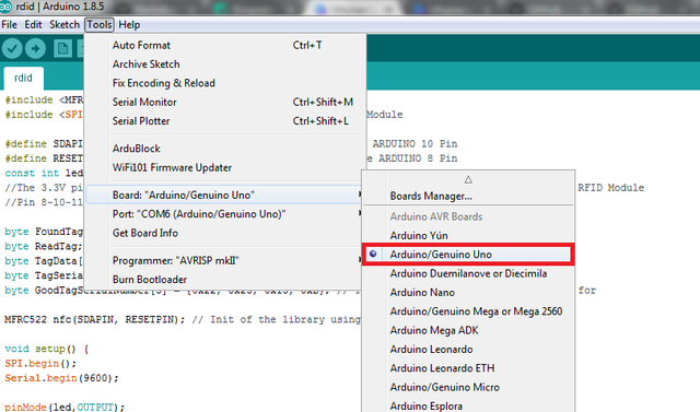
- Open your Arduino IDE, change your board to Arduino Uno: Go to Tools > Board: > Arduino/Genuino Uno
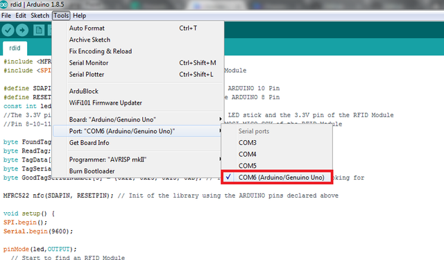
- And also, change the Port settings: Go to Tools > Port: > COM6 (Arduino/ Genuino Uno)
- Install the MFRC522 library this will be used to initialize our pins in Arduino. Go to Sketch > Include Library > Manage Libraries
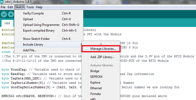
- A new window will appear and search for "MFRC522" then click Install.
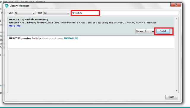
Step 3: The Code
Include the RC522 Library
#include <MFRC522.h>
Used for communication via SPI with the Module
#include <SPI.h>
RFID Module SDA Pin is connected to the pin 10
RFID Module RST Pin is connected to the pin 8
LED is connected to the pin 4
#define SDAPIN 10
#define RESETPIN 8
#define LED 4
Initializing all the variables
byte FoundTag; // Variable used to check if Tag was found
byte ReadTag; // Variable used to store anti-collision value to read Tag information
byte TagData[MAX_LEN]; // Variable used to store Full Tag Data
byte TagSerialNumber[5]; // Variable used to store only Tag Serial Number
byte GoodTagSerialNumber[5] = {0x22, 0x23, 0x15, 0xD}; // The Tag Serial number we are looking for
Initialization of the library using the ARDUINO pins declared above
MFRC522 nfc(SDAPIN, RESETPIN);
Code inside the setup()
void setup() {
  SPI.begin(); // Opens up the communicationto the serial monitor in Arduino IDE
  Serial.begin(9600);
  pinMode(LED, OUTPUT); // Setup the pin 4 to be the output of LED
// Start to find an RFID Module
  Serial.println("Looking for RFID Reader");
  nfc.begin();
  byte version = nfc.getFirmwareVersion(); // Variable to store Firmware version of the Module
// If can't find an RFID Module
  if (! version) {
    Serial.print("Didn't find RC522 board.");
    while (1); //Wait until a RFID Module is found
  }
  // If found, print the information about the RFID Module
  Serial.print("Found chip RC522 ");
  Serial.print("Firmware version: 0x");
  Serial.println(version, HEX);
  Serial.println();
}
Code inside the loop()
String GoodTag = "False"; // Variable used to confirm good Tag Detected
// Check to see if a Tag was detected
 // If yes, then the variable FoundTag will contain "MI_OK"
  FoundTag = nfc.requestTag(MF1_REQIDL, TagData);
if (FoundTag == MI_OK) {
    delay(200);
    // Get anti-collision value to properly read information from the Tag
    ReadTag = nfc.antiCollision(TagData);
    memcpy(TagSerialNumber, TagData, 4); // the tag information in the TagSerialNumber variable
// Check if detected Tag has the right Serial number we are looking for
    for (int i = 0; i < 4; i++) {
      if (GoodTagSerialNumber[i] != TagSerialNumber[i]) {
        break; // if not equal, then break out of the "for" loop
      }
      if (i == 3) { // if we made it to 4 loops then the Tag Serial numbers are matching
        GoodTag = "TRUE";
      }
    }
    if (GoodTag == "TRUE") {
      Serial.println("Success!");
      Serial.println();
      digitalWrite(LED, HIGH);
      delay(1500);
    }
else {
      Serial.println("TAG NOT ACCEPTED");
      Serial.println();
      digitalWrite(LED, LOW);
    }
    delay(500);
  }
}
My Circuit
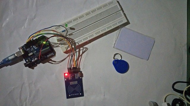
When the card tag is scanned the LED will light up.
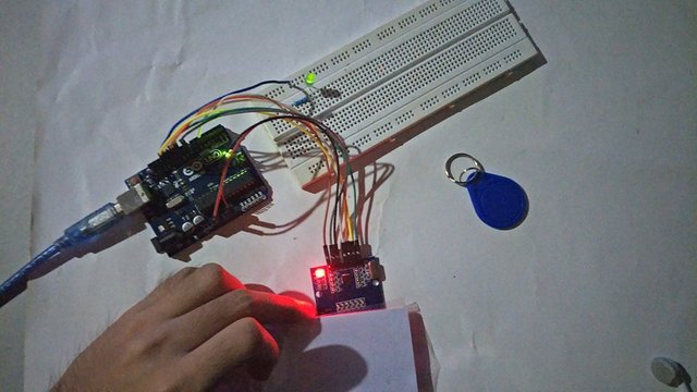
When the keychain tag is scanned the LED will be off.
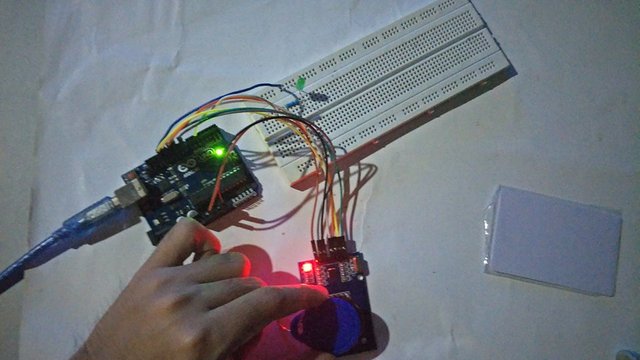
Tip to remember: The range of RFID to detect a tag depends on the fequency of what the module has, so if you need a longer range in your project choose the higher frequency.
Posted on Utopian.io - Rewarding Open Source Contributors
The contribution has been accepted.
[utopian moderator]
Downvoting a post can decrease pending rewards and make it less visible. Common reasons:
Submit
Thank you sir
Downvoting a post can decrease pending rewards and make it less visible. Common reasons:
Submit
very intersting you have my vote!!!!
Downvoting a post can decrease pending rewards and make it less visible. Common reasons:
Submit
thanks bro!
Downvoting a post can decrease pending rewards and make it less visible. Common reasons:
Submit
Another exceptional post right there @kimp0gi!
You have just proven how good the engineering studs our university has produced and how good engineers in the future we could be. You are a very important asset of the steemph.cebu community.
Downvoting a post can decrease pending rewards and make it less visible. Common reasons:
Submit
wohoo! im just next to you @japh hahaha
Downvoting a post can decrease pending rewards and make it less visible. Common reasons:
Submit
Hey @kimp0gi I am @utopian-io. I have just upvoted you!
Achievements
Suggestions
Get Noticed!
Community-Driven Witness!
I am the first and only Steem Community-Driven Witness. Participate on Discord. Lets GROW TOGETHER!
Up-vote this comment to grow my power and help Open Source contributions like this one. Want to chat? Join me on Discord https://discord.gg/Pc8HG9x
Downvoting a post can decrease pending rewards and make it less visible. Common reasons:
Submit