Learn to traceroute and troubleshoot network problems.
What Will I Learn?
- You will learn about traceroute.
- You will learn to design network for traceroute.
- You will learn to troubleshoot network problems with traceroute.
- You will learn about traceroute output characters used to know the nature of problem.
Requirements
- Windows 7(32 bit) or more, Any Linux Distro - Debian/ Ubuntu are provided and supported
- Cisco IOS device images.
- GNS3 Software.
Difficulty
Difficulty is at an intermediate level.
Resources
- Website http://www.gns3.com/
- Github Code Link: https://github.com/GNS3/gns3-gui
- Installation: https://gns3.com/support/docs
- License: GNU General Public License
About GNS3
Graphical Network Simulator-3 (shortened to GNS3) is a network software emulator first released in 2008. It allows the combination of virtual and real devices, used to simulate complex networks. It uses Dynamips emulation software to simulate Cisco IOS.
GNS3 is used by many large companies including Exxon, Walmart, AT&T and NASA, and is also popular for preparation of network professional certification exams. As of 2015, the software has been downloaded 11 million times.
Description
GNS3 or Graphical Network Simulator is a simulator used for virtual network designs, This software is an open source software and supports Cisco routers and switches by using an emulator known as dynamips. In this Video Tutorial you will learn to trace the route to various ports of the IOS devices. Traceroute command is used to identify the path followed by a packet to reach its destination. It gives us the path followed from source host to destination host and also helps to know if the path is reachable or not. Traceroute therefore can be used to troubleshoot the network as it tells us about the path failures if there are any with the help of characters where each character has its own assigned meaning. To be able to use it you will have to follow the steps given below.
Step 1
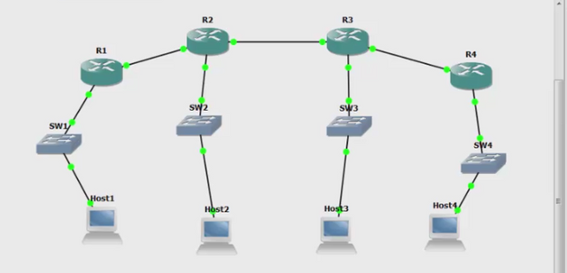
The Step one will be to design a network so that the user can trace the paths which form the network. In the video tutorial I have used four routers R1, R2, R3, R4 which are connected to four switches and these switches are connected to hosts. To be able to start the traceroute you will have to assign IP addresses to the ports of the four routers which are connected in the network. So, the next step will be to start the IP addressing. Here I will upload an image to help you get idea of the network.
Step 2
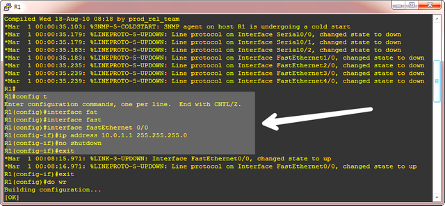
Step two as explained above will be to do the IP addressing of the ports which are connected to each other in the network. So first we will look into Router 1, You will look for the port which is connected to the Router 2, Here port fastethernet 0/0 is connected to R2. You will have to configure it. The configuration for the fastethernet 0/0 in this network is shown below.
interface fastethernet 0/0
ip address 10.0.1.1 255.255.255.0
no shutdown
exit
do wr
The configuration is also shown with an image below.
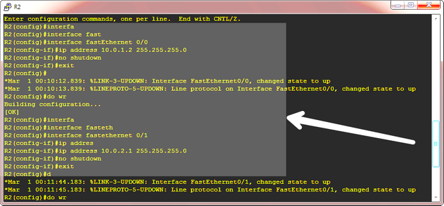
- You will now look for ports of Router 2 (R2) which are connected to R1 and R3, There will be two ports for that, here the port connected to R2 is fastethernet 0/0 and the port connected to R3 is fastethernet 0/1. You will have to configure these ports. The configuration for the above mentioned ports of R2 in the video tutorial is shown below.
interface fastethernet 0/0
ip address 10.0.1.2 255.255.255.0
no shutdown
exit

interface fastethernet 0/1
ip address 10.0.2.1 255.255.255.0
no shutdown
exit
do wr
This configuration is also shown with an image to relate to the video tutorial.
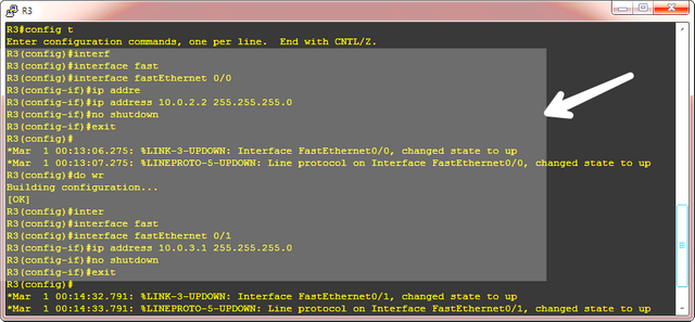
- Similarly for Router 3 the ports to be configured are fastethernet 0/0 port connected to R2 and fastethernet 0/1 port connected to R4. The configuration is shown below.
interface fastethernet 0/0
ip address 10.0.2.2 255.255.255.0
no shutdown
exit

interface fastethernet 0/1
ip address 10.0.3.1 255.255.255.0
exit
do wr
This configuration is also shown with an image.
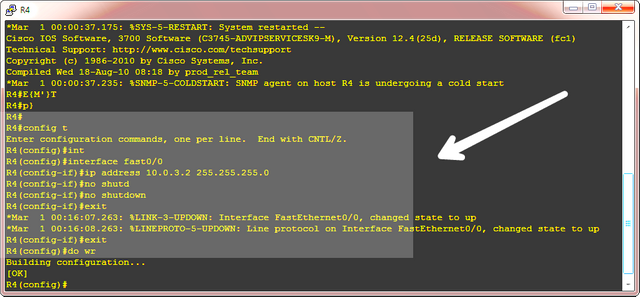
- Router 4 has only one connected port to R3 fastethernet 0/0 port and the configuration is shown below.
interface fastethernet 0/0
ip address 10.0.3.2 255.255.255.0
no shutdown
exit
do wr
The configuration is also shown below.
Step 3
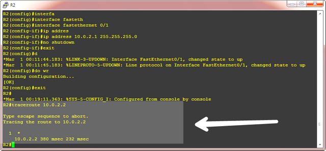
The final step will be to use the traceroute command, In the Video you will find that i have tried to trace the route to IP address 10.0.2.2 from the Router 2, i.e I have used the command from R2 to start tracing the route to 10.0.2.2 address and the command for that will be shown below. Remember the command is used in the privilge mode only.
R2#traceroute 10.0.2.2
This is also shown with an image
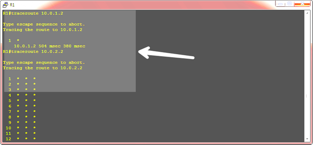
Similarly I have traced route using the R1, I have traced the address 10.0.1.2 which can be shown as below.
R1#traceroute 10.0.1.2
The route is shown is as functional, lets suppose the address 10.0.2.2 fails to respond to the traceroute call from router 1, the configuration for this will be shown below.
R1#traceroute 10.0.2.2
This IP is not able to respond and the output of traceroute is in the form of different characters, here in the video its in the form of ' * ' . The network problem shown by this ' * ' is that the probe has timed out. This can be shown with an image below.
Many other characters may be displayed, I will provide you the list of characters which represent problems of the network. These help to define the problems of the network and help to troubleshoot the network.
'*' - the probe has timed out.
A - administratively prohibited (e.g, with an access-list).
Q - source quench (the destination is busy).
I - user interrupted test.
U - port is unreachable.
N - the network is unreachable.
P - the protocol is unreachable.
T - timeout.
? - unknown packet type.
Video Tutorial
Curriculum
Learn networking with the help of gns3 simulator. Follow the tutorial.
GNS3- Basic Router Configuration (Part 1)
GNS3- Basic Router Configuration (Part 2)
GNS3- Basic Router Configuration (Part 3)
GNS3- Basic Router Configuration (Part 4)
GNS3- Basic Router Configuration (Part 5)
GNS3- Basic Router Configuration (Part 6)
GNS3- Basic Router Configuration (Part 7)
GNS3- Basic Router Configuration (Part 8)
Posted on Utopian.io - Rewarding Open Source Contributors
@neemanbhat, I sent you a lengthy explanation privately in Discord as to why I have rejected this submission. Please refer to this private message?
For reference in this post, this submission has been rejected as it does not follow the following Utopian Rule:
"Tutorials containing process videos, such as gameplay, content creation and simple on-screen instruction will be rejected."
While GNS3 is an open source project, the concepts you are demonstrating in the tutorial are ubiquitous networking functions and concepts. Contributors must submit video tutorials which instruct the unique functions of a specific Open Source project.
I am happy to discuss this further with you.
Need help? Write a ticket on https://support.utopian.io.
Chat with us on Discord.
[utopian-moderator]
Downvoting a post can decrease pending rewards and make it less visible. Common reasons:
Submit