In this instructable i will going to show you how to control 1 digital tube seven segment display on arduino. so what is seven segment display?
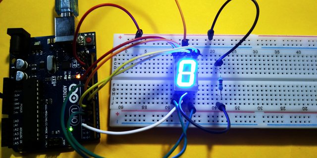
A seven-segment display is a form of electronic display device for displaying decimal numerals that is an alternative to the more complex dot-matrix displays. This displays are widely used in digital clocks, electronic meters, and other electronic devices for displaying numerical information.A seven segment display, as its name indicates, is composed of seven elements. Individually on or off, they can be combined to produce simplified representations of the arabic numerals. and are arranged as a rectangle of two vertical segments on each side with one horizontal segment on the top, middle, and bottom. : source wikipedia
COMPONENTS
CIRCUIT DIAGRAM
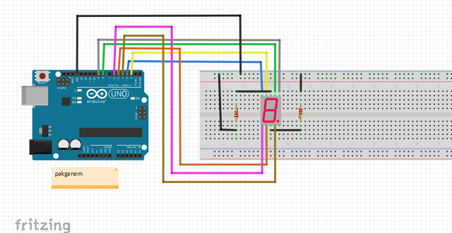
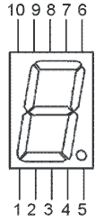
7 segment pin-output
Connect the pins Listed below:
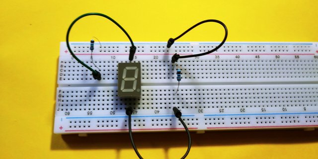
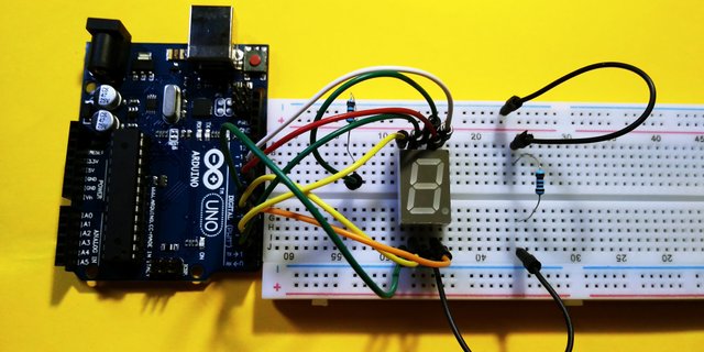
Note that this is a common cathode type of seven segment or the common ground, the 3, 8 output of the seven segment tube is GND for cathode, if yours was common anode then it should be VCC and pin out may be different.
SOFTWARE
Before we work on our sketch, make sure to download the Arduino IDE for your specific operating system. I’ll leave a link to where you can download this software: https://www.arduino.cc/en/Main/Software
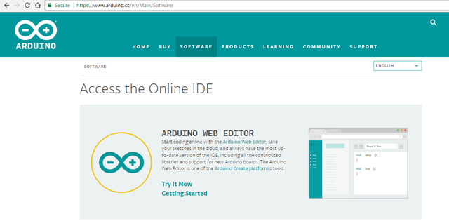
Sketch code for seven segment 1 digital tube common cathode:
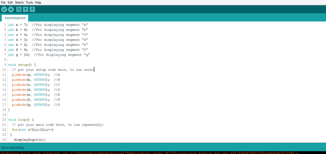
Copy source code here:
``` int a = 8; //For displaying segment "a"int b = 9; //For displaying segment "b"int c = 4; //For displaying segment "c"int d = 5; //For displaying segment "d"int e = 6; //For displaying segment "e"int f = 2; //For displaying segment "f"int g = 3; //For displaying segment "g"void setup() { // put your setup code here, to run once: pinMode(a, OUTPUT); //A pinMode(b, OUTPUT); //B pinMode(c, OUTPUT); //C pinMode(d, OUTPUT); //D pinMode(e, OUTPUT); //E pinMode(f, OUTPUT); //F pinMode(g, OUTPUT); //G}void loop() { // put your main code here, to run repeatedly: for(int i=0;i<10;i++) { displayDigit(i); delay(1000); turnOff(); }}void displayDigit(int digit){ //Conditions for displaying segment a if(digit!=1 && digit != 4) digitalWrite(a,HIGH); //Conditions for displaying segment b if(digit != 5 && digit != 6) digitalWrite(b,HIGH); //Conditions for displaying segment c if(digit !=2) digitalWrite(c,HIGH); //Conditions for displaying segment d if(digit != 1 && digit !=4 && digit !=7) digitalWrite(d,HIGH); //Conditions for displaying segment e if(digit == 2 || digit ==6 || digit == 8 || digit==0) digitalWrite(e,HIGH); //Conditions for displaying segment f if(digit != 1 && digit !=2 && digit!=3 && digit !=7) digitalWrite(f,HIGH); if (digit!=0 && digit!=1 && digit !=7) digitalWrite(g,HIGH);}void turnOff(){ digitalWrite(a,LOW); digitalWrite(b,LOW); digitalWrite(c,LOW); digitalWrite(d,LOW); digitalWrite(e,LOW); digitalWrite(f,LOW); digitalWrite(g,LOW);} ``` Plug-in the arduino uno to your computer then verify compile then upload it to the board. so this is the result.
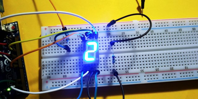
So thats all folks the seven segment displays number 0-9 i will try upload video sooner as possible, This seven segment display can be used for various purposes. Hope this project inspires further experimentation, if you want to learn arduino this blog might help you!. Dont forget to follow mores comming up.
![20180105_182452[1].jpg](https://steemitimages.com/640x0/https://res.cloudinary.com/hpiynhbhq/image/upload/v1515500180/ighy9mdyuiqdqpfrwcxa.jpg)
Posted on Utopian.io - Rewarding Open Source Contributors
Is it LED based?
Downvoting a post can decrease pending rewards and make it less visible. Common reasons:
Submit
Yes its led
Downvoting a post can decrease pending rewards and make it less visible. Common reasons:
Submit
Thanks for reply
Downvoting a post can decrease pending rewards and make it less visible. Common reasons:
Submit
Your contribution cannot be approved because it does not follow the Utopian Rules.
We have already recevied similar coontribution: https://utopian.io/utopian-io/@rfece143/microcontroller-programming-using-mikroc-and-fritzing-for-circuit-design-a-step-by-step-process-in-pic-programming-of-the-basic
You can contact us on Discord.
[utopian-moderator]
Downvoting a post can decrease pending rewards and make it less visible. Common reasons:
Submit
I never see that! By the way thanks:)
Downvoting a post can decrease pending rewards and make it less visible. Common reasons:
Submit