Good day dear readers!
Another tutorial for you to learn today about electronics, in this topic you will be able to know the basic operation of a diode when it is in reversed bias or in forward bias condition. As part of this topic, I will include the terms that are useful to understand the diode operation.
To begin with, here is the definition of terms
♦ Bias –a dc voltage is applied to control the operation of a device
♦ Forward-bias –the current will flow when diode is forward-biased
Materials needed for this topic
♦ Diode
♦ Battery (DC supply)
♦ Resistor
Short Description of the materials
Diode - is a two-terminal electronic component that conducts current primarily in one direction
Resistor – opposes the flow of current
Battery –a dc source consisting of one or more electrochemical cells with external connections
Software
♦ QUCS circuit simulator
What is a Forward-bias Diode Operation
In this condition, the positive terminal of the diode is connected to the positive terminal of the voltage supply making it to be forward bias. The diode will act as a short circuit. It means the diode conducts like a wire in which current will flow through the load.
Simulation of diode in FORWARD-bias condition
Construct the circuit to forward-bias the diode
Open the QUCS software
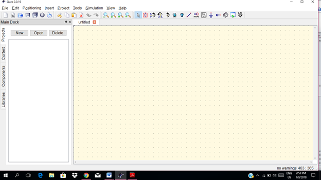
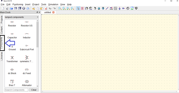
Select all components for the circuit.
Click on the components.
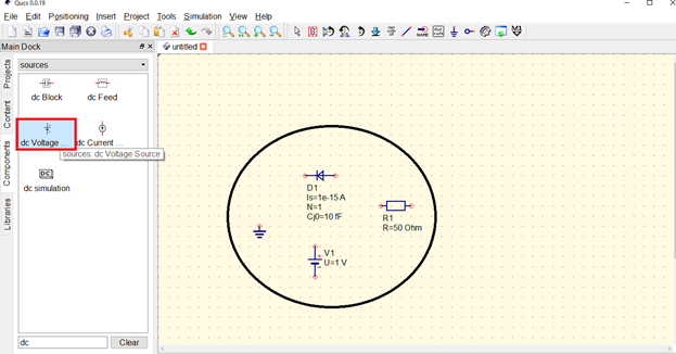
Select the 1 resistor, 1 diode & a supply voltage.
Connect the circuit. Click on wire icon then start the connection.
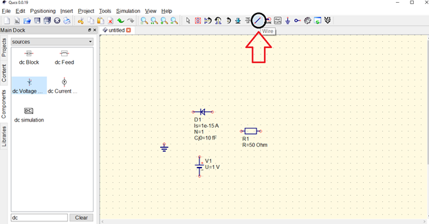
Arrange the components to make it easier to construct.
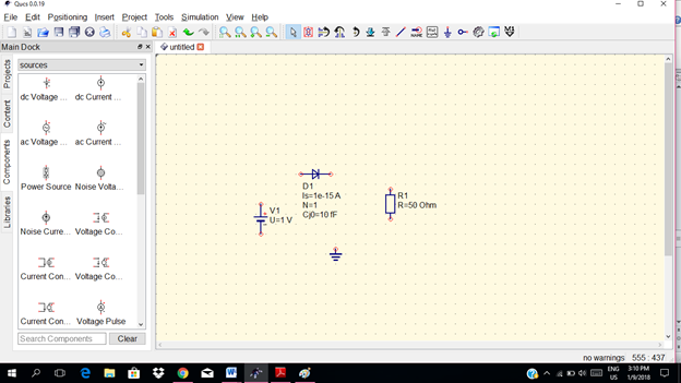
Now this the circuit for forward-bias
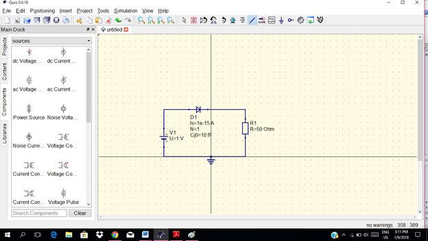
Now for Circuit simulation
Select the simulations in the left side menu. Click on the arrow down figure.
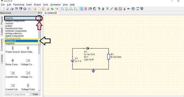
Click on DC simulation.
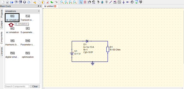
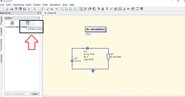
Then put a dc probes across the load resistor.
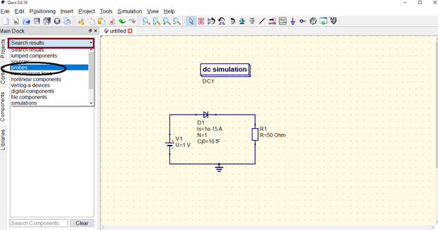
In this tutorial, we will use the dc voltage probes.
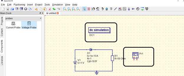
Connect the probes to the load resistor to see the output voltage.
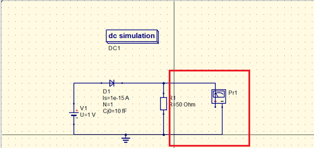
Before starting simulation, set the properties of the dc simulation parameters.
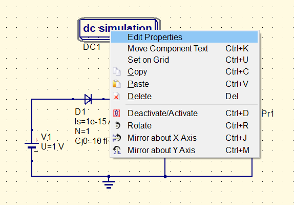
We will set the room temperature 27 degree Celsius . Click apply then ok.
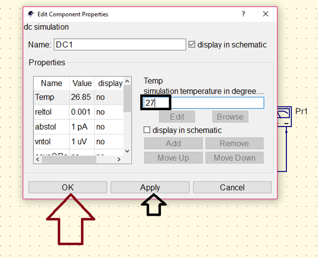
Click simulation at the top menu then select simulate.
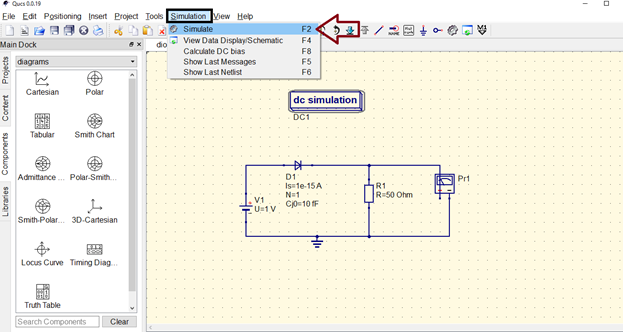
It will display like this below.
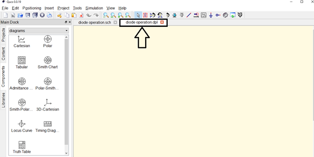
To display the output, we need a diagram. So select diagrams in the menu.
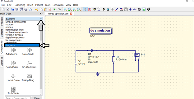
Then choose tabular. Then edit diagram properties will pop up.
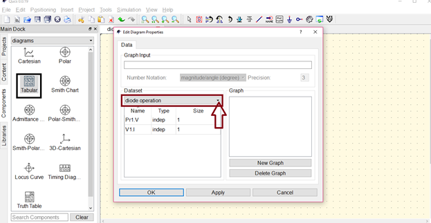
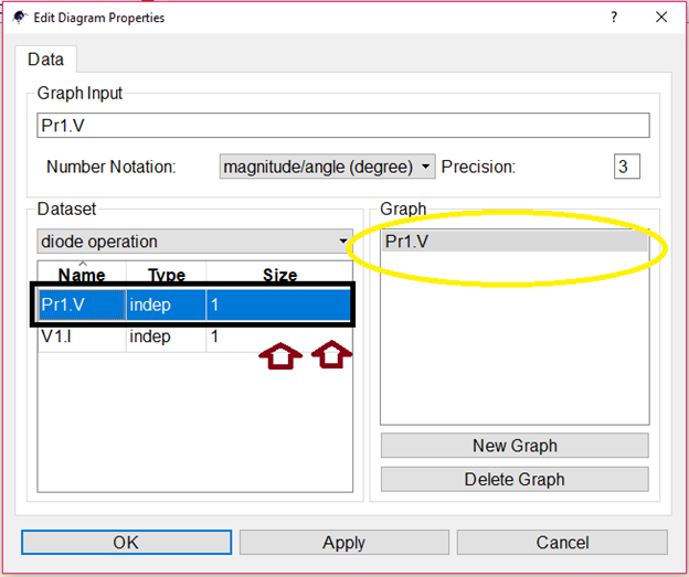
Double click the output at the voltage probes to display on the graph. Then click ok.
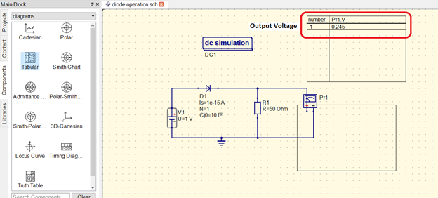
Now in the circuit area, click to display the tabulated output. As you can see in the table, it display an output voltage of 0.245.
Now let us conduct an actual experiment
Materials needed
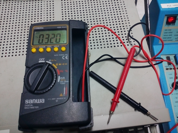
♦ Digital multimeter
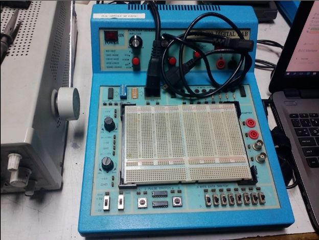
♦ Analog trainer
Components
♦ Resistor
♦ Diode
Actual Connection diagram
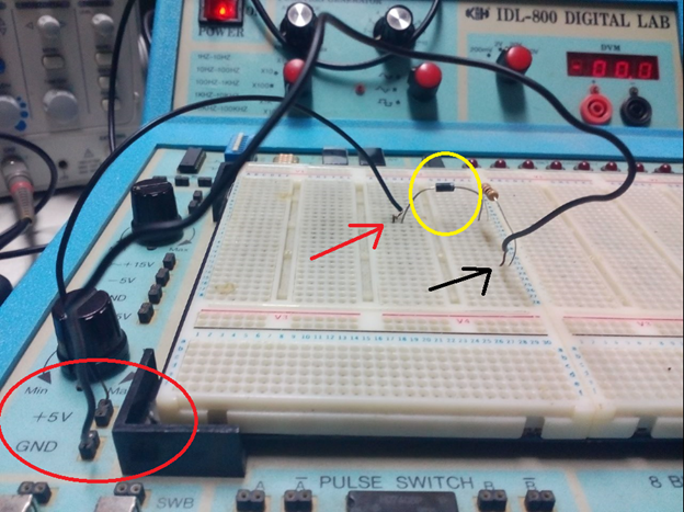
The input of the circuit is 5.07V and connected to the positive terminal of the diode making it in forward bias condition.
I use the analog trainer as an input supply in which I measured 5.07 V using the digital multimeter.
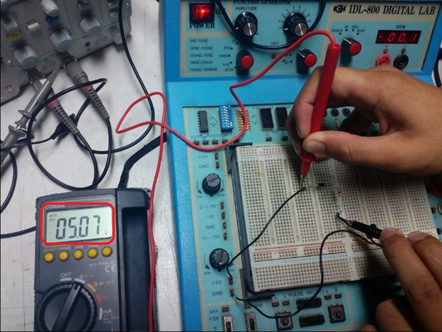
The output will be measured across the load resistor as you can see in the figure below.
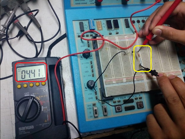
The output is measured using digital multimeter which is 4.41 V it means the diode conducts and allowing current to flow.
If we reverse the connection, the negative terminal of the diode will be connected to the positive input supply. Like in the figure below.
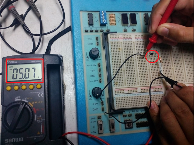
Then the output will be approximately equal to zero.
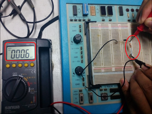
It means in reverse bias connection, the diode acts as an open circuit. No current will flow through the circuit.
Conclusion
In forward bias, the diode acts as closed circuit allowing the circuit to operate.
Application of this topic
In making a power supply, the diode is used as a rectifier in which it converts dc input to ac output base from this diode characteristic. One example of major application of diode is a charger of mobile phones & laptops. In which it converts ac supply to a dc supply that compatible for any electronic devices that needs dc supply.
Thanks for your time!
I hope this will help.
Yours Truly,
@rfece143
Posted on Utopian.io - Rewarding Open Source Contributors
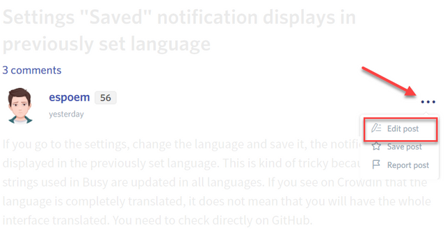
Your contribution cannot be approved yet. See the Utopian Rules. Please edit your contribution to reapply for approval.
You may edit your post here, as shown below:
You can contact us on Discord.
[utopian-moderator]
Downvoting a post can decrease pending rewards and make it less visible. Common reasons:
Submit
sir @shreyasgune I already made experiment and suggestions were added sir
Downvoting a post can decrease pending rewards and make it less visible. Common reasons:
Submit
Thank you for the contribution. It has been approved.
You can contact us on Discord.
[utopian-moderator]
Downvoting a post can decrease pending rewards and make it less visible. Common reasons:
Submit
Hey @rfece143 I am @utopian-io. I have just upvoted you!
Achievements
Suggestions
Get Noticed!
Community-Driven Witness!
I am the first and only Steem Community-Driven Witness. Participate on Discord. Lets GROW TOGETHER!
Up-vote this comment to grow my power and help Open Source contributions like this one. Want to chat? Join me on Discord https://discord.gg/Pc8HG9x
Downvoting a post can decrease pending rewards and make it less visible. Common reasons:
Submit
To simulate a diode in forward-bias using QUCS, first, create a new circuit and place a diode. Connect the anode to a positive voltage source and the cathode to ground. Configure the voltage source to exceed the diode's threshold (typically 0.7V for silicon). Run the simulation to observe current flow. For Zener diodes, repeat the process but connect the Zener diode in reverse-bias to analyze breakdown voltage effects. This approach highlights both standard and Zener diode behaviors in different bias conditions.
Downvoting a post can decrease pending rewards and make it less visible. Common reasons:
Submit