Hello everyone!
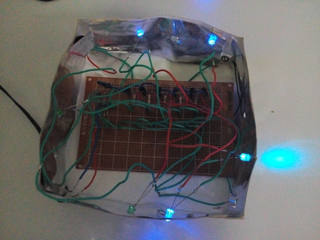
This is another tutorial for creating electronic projects in dealing with sound-lights system. In this tutorial, you will be able to design your own lighting system that could follow the beat of the sound system that you have. For this topic, I will use 6 LED lights only.
Materials needed in this tutorial
♦ condenser microphone
♦ BC547 transistor NPN
♦ resistor
♦ capacitor
♦ LED lights
♦ DC source
♦ Breadboard
♦ soldering lead & soldering iron
♦ universal PCB
Software for circuit layout
♦ Fritzing
Short description for the materials
Condenser Microphone –it is an electronic device that is used to pick-up sound signals then convert this signal into a voltage signal levels
BC547 transistor NPN –a device used to amplify a signal or used as switching device
Resistor –a passive device that oppose the flow of current
Capacitor –a device which stores electrical energy in the electric field
LED –emits lights when activated
Switch –performs on/off
Source –a DC supply that enables the circuit to operate
Soldering iron –is an electronic tool used in construction of a circuit using the soldering lead.
Soldering lead --is a metal alloy when melted used as permanent bond
Circuit construction using FRITZING
1. Open the fritzing
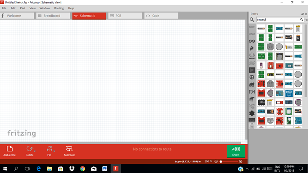
2. Select all the necessary components needed
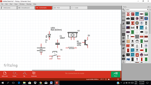
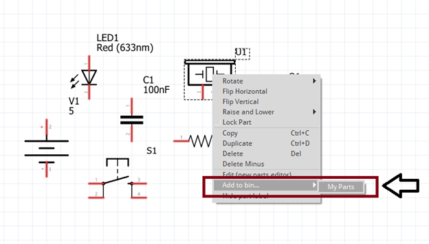
Once you selected all the components, right click each and click add to bin then click My parts. So that all the components will be stored in the mine parts
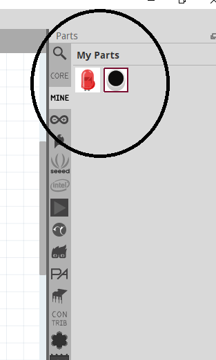
3. Construct the circuit diagram
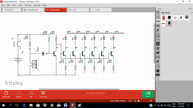
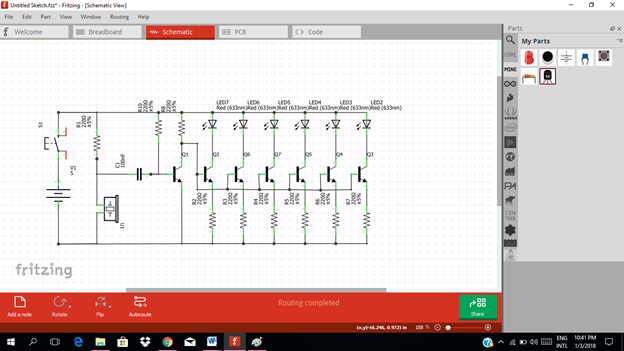
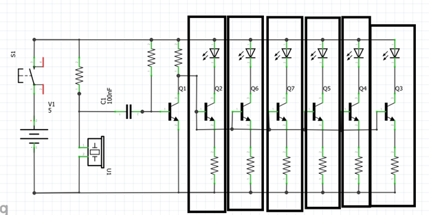
Circuit Explanation of how the signal being transferred and how come the LED lights follow the beat of the sound signal
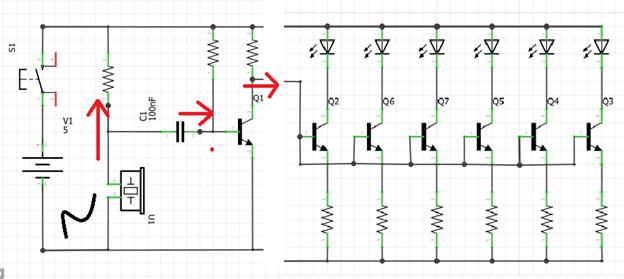
As you can see in the figure above, as the condenser microphone detects the sound signal (color black) it converts it into a certain current level (red arrow) that flows through the resistor and then fed to the base of the transistor. The transistor will performs amplification of signal.
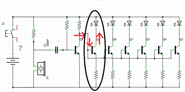
The transistor will amplify this current level to a certain level that could drive the LED lights. As you can see the output of the transistor at the collector terminal is feed to another transistor that is connected to the LED. Once the signal is amplified, it is enough to trigger the LED that will produce lights.
It is connected in parallel so that the same voltage level that could trigger the LED lights.
You can add LED lights as much as you want for your design just connect it in parallel or in the arrays of transistors & LED’s
How does it works
The condenser microphone picks up sound signals and then coverts them into a voltage signal levels which is then fed to the RC filters (resistor-capacitor connection) to filter unwanted sound signal. The use of the transistor is to amplify the filtered sound signals from the filters. Then the amplified signal is then fed to the following arrays of transistor which acts as an amplifier and makes the led glows according to the sound pattern. This will create a lighting system that follows every beat of the sound signal it detects.
Construction of circuit in the FRITZING breadboard
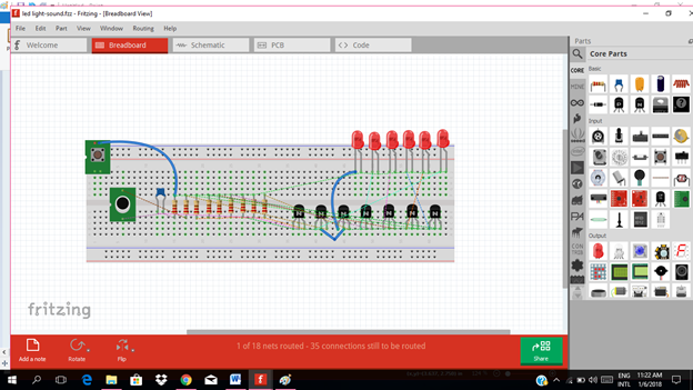
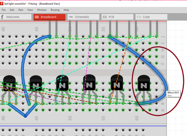
In connecting the pins in the breadboard, just click and hold the base of pin (or the hole in the breadboard where pin was placed) then drag to where it must be connected. Like in the figure below.
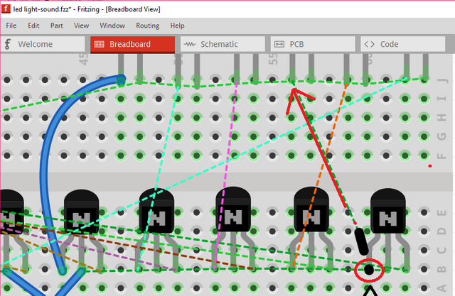
After that, a wire will be displayed like this.
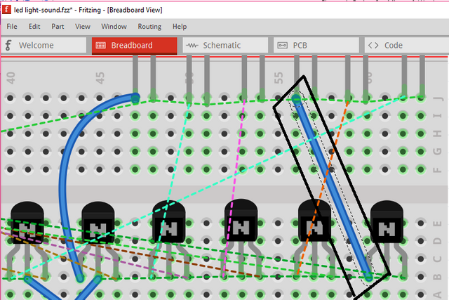
Then if you want to bend this wire, just press ctrl+ click & hold the wire then bend it wherever you want.
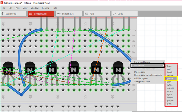
If you want to change the color of the wire, just click the wire then choose wire color. Then you can select the color you want. For example green.
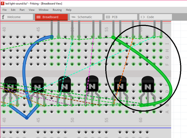
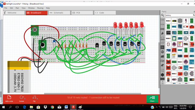
After doing this to all the connection, the circuit in the breadboard will look like this below.
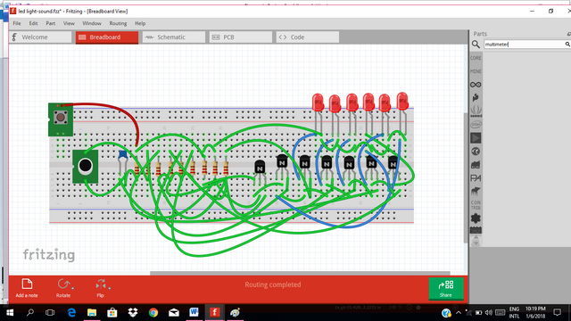
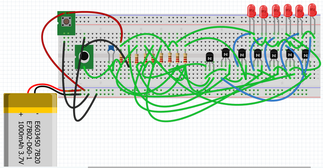
We will add the supply battery. Now the circuit will look like this below.
Actual Project: Using the actual universal PCB for the circuit
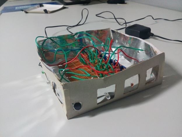
As you can see in the actual photo of the project, it is being soldered in the universal PCB. It is easy to solder the circuit when using the universal PCB because you don’t need to make your PCB layout you just arrange the circuit like you are using a breadboard.
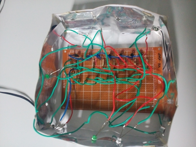
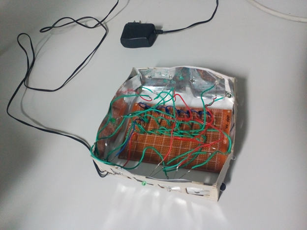
In the actual project, I used the charger as the supply of the circuit. You can use a 9V battery also.
Please visit this link for more tutorial about fritzing
Video testing of the circuit
Application of this project
This is very applicable in a club or even in our home and also inside a sports car in which there is a sound system. It is nice to see lights that follow the beat of the sound it detects. If you love music, then put lights on it.
If you find it interesting, just follow the steps for you to create your own sound-light system.
Thanks for your time. Have a good day everyone.
Yours Truly,
@rfece143
Posted on Utopian.io - Rewarding Open Source Contributors
Interesting!!! Nice idea!!! Keep it up mate!!
Downvoting a post can decrease pending rewards and make it less visible. Common reasons:
Submit
thanks @aribalcristian
Downvoting a post can decrease pending rewards and make it less visible. Common reasons:
Submit
Thank you for the contribution. It has been approved.
You can contact us on Discord.
[utopian-moderator]
Downvoting a post can decrease pending rewards and make it less visible. Common reasons:
Submit
Your contribution cannot be approved because it is not as informative as other contributions. See the Utopian Rules. Contributions need to be informative and descriptive in order to help readers and developers understand them.
You can contact us on Discord.
[utopian-moderator]
Downvoting a post can decrease pending rewards and make it less visible. Common reasons:
Submit
sir @shreyasgune i already put some important details on my post ..
Downvoting a post can decrease pending rewards and make it less visible. Common reasons:
Submit
The tutorial is good one. It requires only small improvements:
Downvoting a post can decrease pending rewards and make it less visible. Common reasons:
Submit
sir @shreyasgune ..all your suggestions sir has been added..please take a look..by the way thanks for your suggestions sir.
Downvoting a post can decrease pending rewards and make it less visible. Common reasons:
Submit
Hey @rfece143 I am @utopian-io. I have just upvoted you!
Achievements
Suggestions
Get Noticed!
Community-Driven Witness!
I am the first and only Steem Community-Driven Witness. Participate on Discord. Lets GROW TOGETHER!
Up-vote this comment to grow my power and help Open Source contributions like this one. Want to chat? Join me on Discord https://discord.gg/Pc8HG9x
Downvoting a post can decrease pending rewards and make it less visible. Common reasons:
Submit