What Will I Learn?
At the end of this tutorial:
♦ The readers will be able to understand and construct the phase shift oscillator circuit
♦ The readers will be able to know how circuit works
♦ Learn to apply the circuit in the future electronic projects
Introduction
What is a phase shift oscillator?
A phase shift oscillator or otherwise known as RC oscillator is an oscillator circuit in which the input signal is shifted to 180 degrees as it flows through the amplifier stage and shifted again through the second inverting stage, a total of 360 degrees phase shift.
You can read more here
Requirements
Electronic Components
♦ Resistor
♦ Capacitor
♦ Op-amp
♦ Oscilloscope
♦ Connecting wires
Software
♦ Maxwell Circuit Simulator
Difficulty
♦ Intermediate
Tutorial Contents
Using the Maxwell circuit simulator software, we will create our circuit diagram, explain how the circuit works and simulate the circuits.
Part I. Schematic Diagram
So first let us construct our circuit diagram.
Open the Maxwell circuit simulator.

Select all the necessary components. We need 3 capacitors , 4 resistors and 1 op-amp. In placing the components, just click on it then click to the circuit area then drag anywhere you want to place the component.
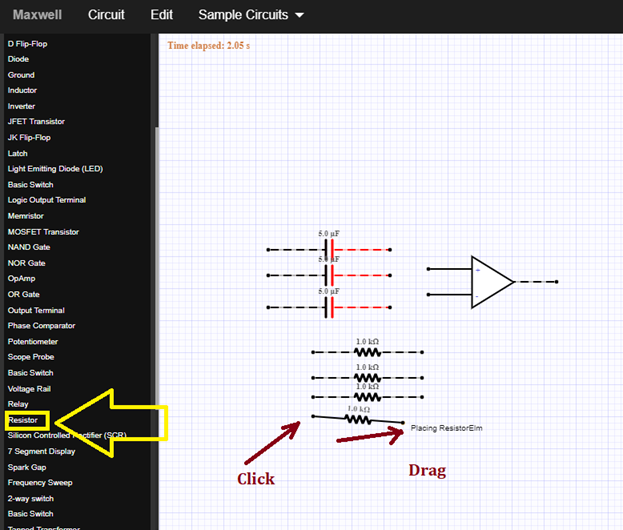
These are the components that we need for our phase shift oscillator circuit.
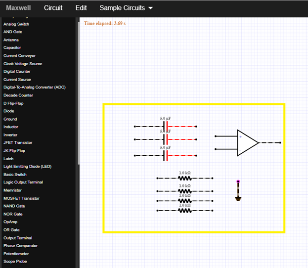
Arrange all the components before constructing or connecting the circuit. We will create a three stage of RC connection.
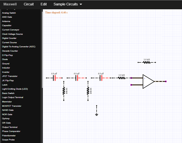
There are three RC connections as you can see in the figure below. This RC tandem has a role in phase shifting the signal.
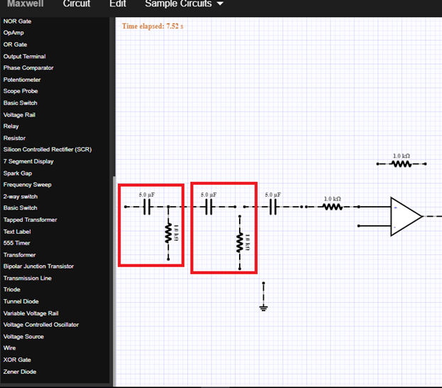
So now, connect the RC in cascade as you can see in the figure below.
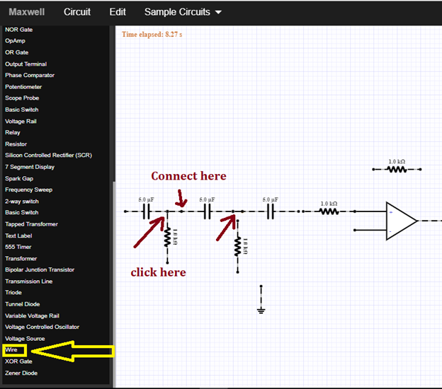
At the amplifier circuit, we need a feedback resistor connected to the positive terminal of the op-amp and to the output terminal.
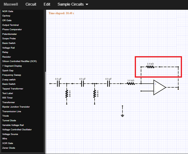
Now this is our phase shift oscillator circuit.
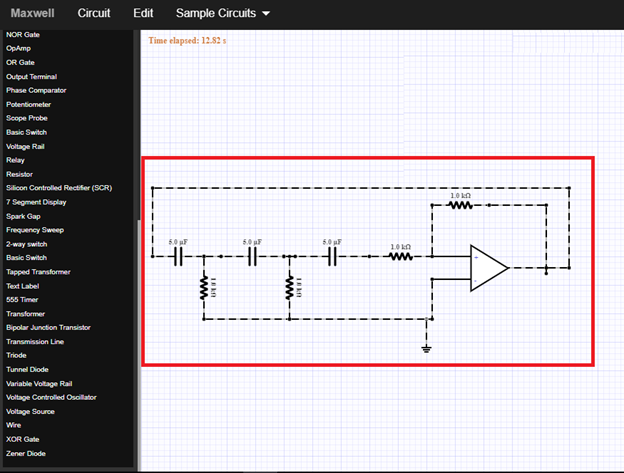
Part II. How the circuit works
This circuit is composed of three RC stage networks; each network has an output voltage “leads” the input voltage by some angle less than 90 degrees.
As you can see in the figure below.
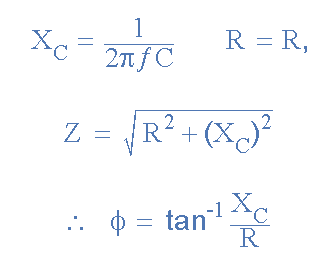
These three RC stages has a phase shift of 90 degrees with additional 60 degrees in each successive RC network.
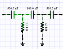
These three RC stages are cascaded together to get the required slope for a stable oscillation frequency. The feedback loop phase shift is -180 degrees when the phase shift of each stage is -60 degrees.
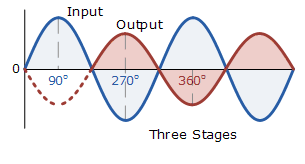
How does it work?
This phase shift oscillator circuit produces a sine wave output signal using regenerative feedback obtained from the resistor-capacitor combination. This regenerative feedback from the RC network is due to the ability of the capacitor to store an electric charge, similar to the LC tank circuit.
The resistor-capacitor feedback network can be connected as shown below to produce a leading phase shift or interchanged to produce a lagging phase shift the outcome is still the same as the sine wave oscillations only occur at the frequency at which the overall phase-shift is 360 degrees.
While the feedback is connected to the inverting input of the op-amp, the operational amplifier is therefore connected in its “inverting amplifier” configuration which produces the required 180 degrees phase shift while the RC network produces the other 180 degrees phase shift at the required frequency.
Part III. Circuit Simulation
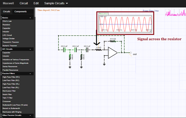
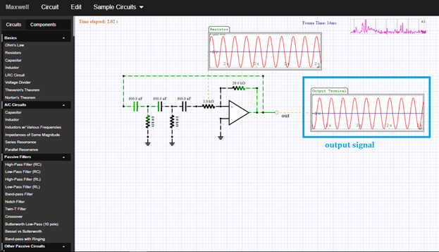
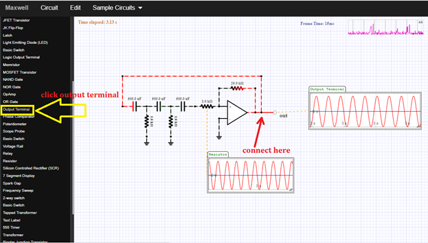
For simulation, just click on the output terminal then connect it to the output node of the circuit as shown below.
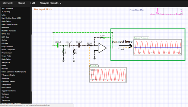
Then click on the scope probe to display and connect the oscilloscope to the output terminal of the circuit. Then the oscilloscope will automatically display the output waveform as you can see in the figure.
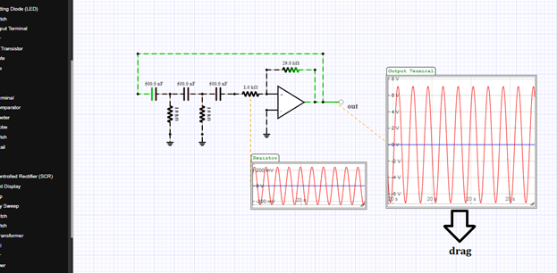
You can adjust the output by dragging it downward or sideward depends on your desired display.
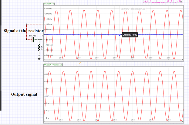
Same process in displaying the input signal in the oscilloscope, and it will look like this above. As expected, the output is 360 degrees out of phase.
Application
The readers can make their own phase shift oscillator circuit that can be used for generating signals over a wide frequency range.
Curriculum
Here are my other tutorials for a circuit simulation of electronic circuits that may help you understands circuit operation.
Posted on Utopian.io - Rewarding Open Source Contributors
Hi! I am a robot. I just upvoted you! I found similar content that readers might be interested in:
https://www.electronics-tutorials.ws/oscillator/rc_oscillator.html
Downvoting a post can decrease pending rewards and make it less visible. Common reasons:
Submit
I will be featuring it in my weekly #technology curation post for the @minnowsupport project and the Tech Bloggers' Guild! TBG is a new group of Steem tech bloggers and content creators looking to improve the overall quality of the niche.
If you wish to not be featured in the curation post this Saturday please let me know. Keep up the hard work and I hope to see you at the Tech Bloggers' Guild!
Downvoting a post can decrease pending rewards and make it less visible. Common reasons:
Submit
Thats great...yes you can..:-)
Downvoting a post can decrease pending rewards and make it less visible. Common reasons:
Submit
Your contribution cannot be approved because it does not follow the Utopian Rules.
You can contact us on Discord.
[utopian-moderator]
Downvoting a post can decrease pending rewards and make it less visible. Common reasons:
Submit