What Will I Learn?
At the end of this tutorial:
♦ The readers will be able to understand and construct the voltage doubler circuit
♦ The readers will be able to know how circuit works
♦ Learn to apply the circuit in the future electronic projects
Introduction
What is a voltage doubler?
Voltage doubler is a multiplier circuit that has a multiplication factor of two. This circuit doubles the input signal as it passes through the diode-capacitor connection.
You can read more here
Requirements
Electronic Components
♦ Resistor
♦ Capacitor
♦ Diode
♦ AC Source
♦ Oscilloscope
♦ Connecting wires
Software
♦ Maxwell Circuit Simulator
Difficulty
♦ Intermediate
Tutorial Contents
Using the Maxwell circuit simulator software, we will create our circuit diagram, explain how the circuit works and simulate the circuits.
Part I. Schematic Diagram
So first let us construct our circuit diagram.
Open the Maxwell circuit simulator.

Select all the necessary components. We need 1 ac source, 2 diodes, 2 capacitors and 1 resistor. In placing the components, just click on it then click to the circuit area then drag anywhere you want to place the component.
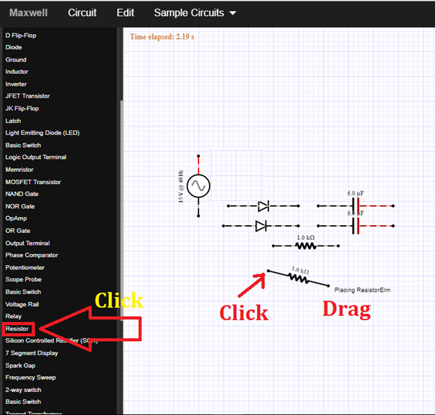
These are the components that we need for our voltage doubler circuit.
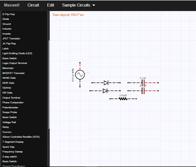
Arrange all the components before constructing or connecting the circuit. The input source will be connected to the diode and capacitor.
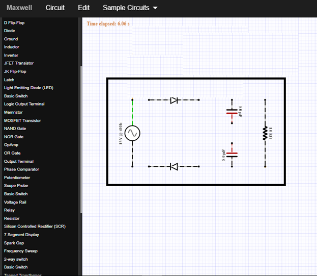
Now let us connect the circuit. The source must be connected to the diode-capacitor connection, then another diode-capacitor tandem to be connected in series with the first tandem. It will look like this below.
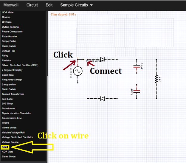
The source must be connected to the diode (positive terminal) and to the capacitor. It will form a series circuit. As you can see in the figure below.
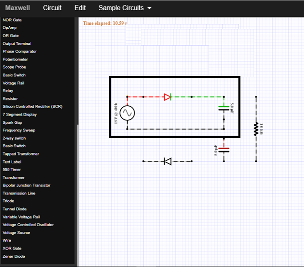
At the lower part of the circuit, connect the diode and capacitor in series then connect it to the first circuit. It will look like this below.
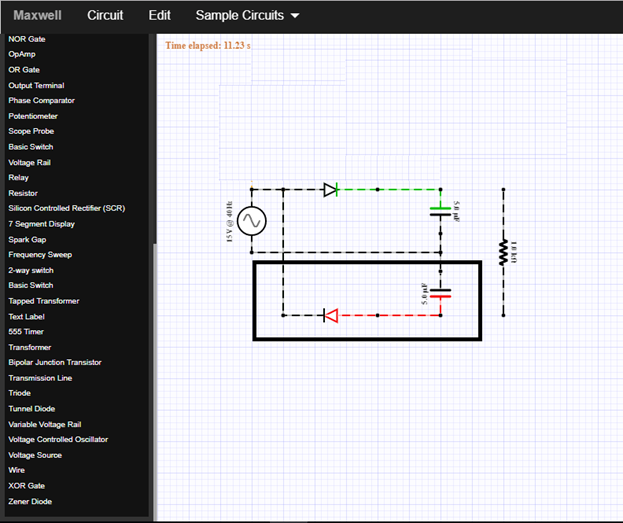
To measure the output signal, we need to connect a resistor in parallel with the series connection between the two capacitors.
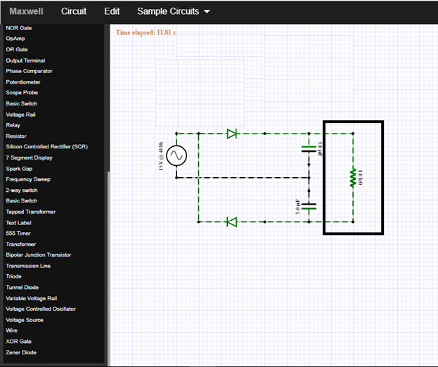
Now this is our final circuit for the voltage doubler.
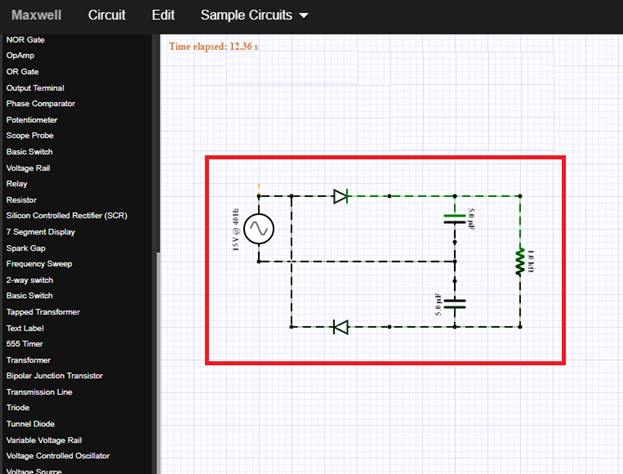
Part II. How the circuit works
To analyze this circuit, let us divide the circuit or vary the circuit to explain it in details.
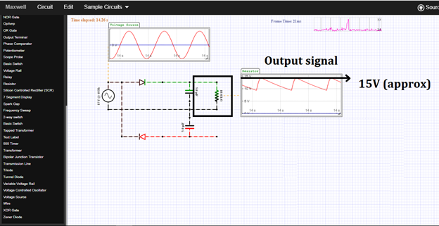
To understand the circuit clearly, let us open the wire connection at the bottom of the circuit then the load resistor will be connected in parallel with the capacitor as you can see in the figure above.
The input ac voltage has a peak voltage of 15 V, and it is connected in series with the diode and capacitor. The diode-capacitor connection will give a dc output equivalent to the peak to peak voltage of the input signal.
How does it work?
The circuit shows a half wave voltage doubler. During the negative half cycle of the sinusoidal input waveform, the diode is forward biased and conducts charging up the pump capacitor, to the peak value of the input voltage.
Because there is no return path for capacitor to discharge into, it remains fully charged acting as a storage device in series with the voltage supply. That is why the output is approximately equal to 15V.
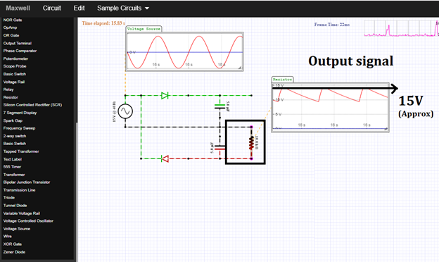
While during the positive half cycle, the upper diode is reverse biased blocking the discharging of upper capacitor while the lower diode is forward biased charging up lower capacitor. But because there is a voltage across upper capacitor already equal to the peak input voltage, lower capacitor charges to twice the peak voltage value of the input signal.
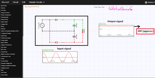
The output signal is simple the combined output during negative half cycle and positive half cycle of the input signal. That is why it is 30V approximately.
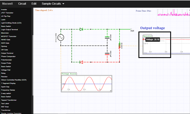
As you can see in the figure, the real output voltage is 28.16V due to the voltage across the two diodes. This is the expected output because the voltage drop of the diode is 0.7V, when it is silicon diode. So 30V -1.4V it is equal to 28.6V.
During the half cycle of the input signal, the upper diode charges the upper capacitor to a dc voltage equivalent to 15V. Then on the positive half cycle of the input signal, the lower diodes conducts and adds the 15V that stored from the upper capacitor and transfer it all to the lower capacitor.
That is why the voltage across the capacitor is equal to twice the peak voltage which is 15V.
Part III. Circuit Simulation
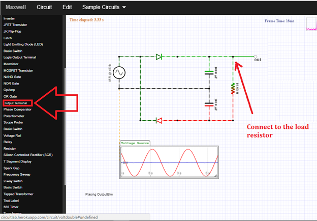
For simulation, just click on the output terminal then connect it to the output node of the circuit as shown below.
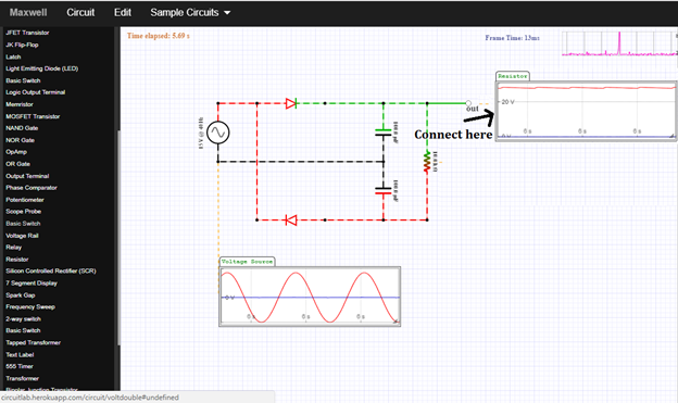
Then click on the scope probe to display and connect the oscilloscope to the output terminal of the circuit. Then the oscilloscope will automatically display the output waveform as you can see in the figure.
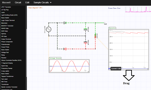
You can adjust the output by dragging it downward or sideward depends on your desired display.
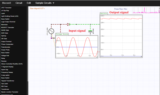
Same process in displaying the input signal in the oscilloscope, and it will look like this above. As expected, the output is twice the input signal.
Application
The readers can make a voltage multiplier circuit that allows higher voltages to be created from a low voltage power source without a need for an expensive high voltage transformer as the voltage doubler circuit makes it possible to use a transformer with a lower step up ratio than would be need if an ordinary full wave supply were used.
Curriculum
Here are my other tutorials for a circuit simulation of electronic circuits that may help you understands circuit operation.
Posted on Utopian.io - Rewarding Open Source Contributors
no diodes in circuit
Downvoting a post can decrease pending rewards and make it less visible. Common reasons:
Submit
Thank you for the contribution. It has been approved.
You can contact us on Discord.
[utopian-moderator]
Downvoting a post can decrease pending rewards and make it less visible. Common reasons:
Submit
thanks @jestemkioskiem
Downvoting a post can decrease pending rewards and make it less visible. Common reasons:
Submit
Hey @rfece143 I am @utopian-io. I have just upvoted you!
Achievements
Suggestions
Get Noticed!
Community-Driven Witness!
I am the first and only Steem Community-Driven Witness. Participate on Discord. Lets GROW TOGETHER!
Up-vote this comment to grow my power and help Open Source contributions like this one. Want to chat? Join me on Discord https://discord.gg/Pc8HG9x
Downvoting a post can decrease pending rewards and make it less visible. Common reasons:
Submit