What You Will Learn?
- How to simulate using Proteus
- Using a microcontroller on proteus
- Simulating with Multimism
- Working with Arduino
Requirements
- A Laptop or a Desktop PC
- Proteus Simulating Software
- Multimism Software
Difficulty
- Advanced
Simulations are best done on computer using software like proteus multisim. Before simulating a circuit, you need to understand how to interpret a circuit diagram after which you can connect the components on the software and run to see results.
Simulating with proteus
Proteus is a software where you can design circuit, see the result, design the PCB layout of the circuit, see the 3d visualization of the circuit and even print the PCB layout
➢ Installing the software:

You can download the software from getintopc.com, 4shared.com or just search on google using Proteus 8.5
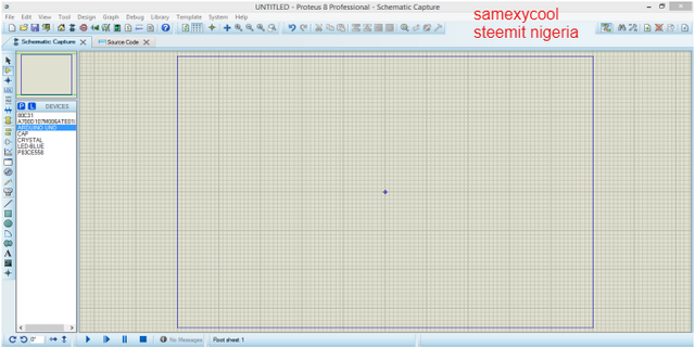
➢ The interface
In the version 8.5 of the software:
The first icon is the schematics design the second is for PCB design the third icon allows you to see a
3d visualization of your circuit
On the left-hand side there are tools for picking, measurement, labelling your component, adding a new component, Below the environment are tools you can use to run, pause and stop your simulations. You can also rotate your component with the rotate tools
➢ Components
Picking your component is easy click on this icon on the left hand side of the environment then
click on P to pick the components this will take you to a box where you can search for the component, for example type in the word RES for a resistor then double click on it to take it to your selection bar after doing this for all the component you want to use click on ok to take you back to the environment
➢ Running your circuit
After connecting the components together on the lower part of the software click on the play icon to run, the pause icon pauses your simulation, the stop icon stops the simulation
➢ Adding a new component
Before adding a new component, you need to download the datasheet of that component You can download datasheet from www.electroschematics.com/tag/ic-datasheet-circiuts/ Now design the component using the datasheet with the following steps:
- Go to the 2D tool click and drag it to your desired size over your workspace.
- Go to your device pin mode tool select default and insert the pins on the box you’ve drawn.
- Double click on the first pin a dialog box pops out type in the name of the pin and the number the select the type of the pin (input, output or power pins) after this click ok.
- Click on the 2D graphics marker mode from the toolbar select origin the place it at the centre of your component this makes it easy to rotate the component
- Drag over your design the click make device on the bar a window will appear from this enter the device name and a prefix then click on next it will take you to where you select the package
- Click on add/edit and select add at the top check the package name from your datasheet and type in the name in the search bar, select the package and click ok
- Then click on assign package then next check the name again and click on next
- You can link your component with it datasheet by typing the name of the datasheet and typing in the path of the document then click on next
- Enter the device categories (analog ic’s, capacitors, resistors etc.), a subcategory, and a manufacturer then type in a little description of the component and click ok to finish. You can now locate the component by picking it from the library.
➢ PCB layout
Clicking this icon takes you to the PCB design environment.
First place your component by clicking on then select the component and place it on the environment.
- Click on the 2D icon then select board edge from the lower part of your draw it around your circuit then go to the menu bar
- Click on technology from the dropdown menu select set layers’ usage then untick all marked bars.
- Click on done after that click on technology again select set layers’ pairs and select bottom copper for all bars then click on ok.
- Click on tools on the menu bar and select auto-router.
➢ Printing PCB layout
Go to output click on export select Export Adobe pdf file select mirror reflection and click ok this will open Adobe reader with your PCB
➢ Using a microcontroller on proteus
From the pick component you can search for any microprocessor or microcontroller you need by typing in the name. Proteus allows you to program the microcontroller and simulate right- click on the component and select edit source code then select the complier you want to use and click ok then type in your program click on build from the menu bar and select build project this will load the program file into the microcontroller then you can simulate.
➢ Downloading more libraries to proteus
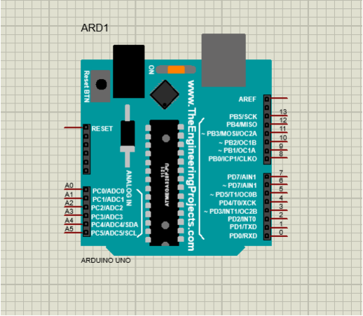
There are some missing components on proteus like the Arduino library, some sensors like ultrasonic, PIR, gas, smoke, Bluetooth module, Wi-Fi module etc. they can be downloaded from this site www.theengineeringprojects.com after downloading unzip the files to your library folder, for example unzip in C:\ProgramFiles(x86)\LabcenterElectronics\Proteus8 Professional\LIBRARY
➢ Working with Arduino

Arduino is an easy to use hardware, it consists of a board which can be programed, it has an open-source software(IDE) which can be used to write and upload the computer code to the board program it. There are different types of arduino board which are based on the number of input and output pins they include Arduino Uno, pro, Ethernet lilypad Leonardo etc. these are all on proteus to enable simulate. After unzipping the arduino library go to proteus software and to pick the Arduino.
Before running a simulation with arduino on proteus you need the ardunio IDE which will enable you to program the arduino. Write the program on the IDE compile it, it will be saved automatically in a folder find the hex file in this folder C:\Users\your username\AppData\Local\Temp\arduino_build_913174.
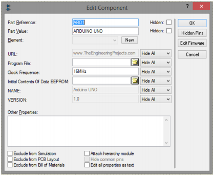
After designing your circuit right click on arduino and select program file locate the above folder the select the hex file of your program then run your circuit

Simulating with Multisim
Multisim is also a software used for simulation below are step to enable you simulate. The software can be downloaded from www.getintopc.com search for ni multisim ultiboard and download the software.
➢ Open the software select place the component, then a window appears where you can
search for any component click on the component place it on the workspace then return to the window and select the next component, you can rotate components by using Crtl+ R.
➢ Wring the component
Move your cursor over the component then a crosshair appears click on it then drag and connect the second component.
➢ Simulating your circuit
Select simulate from the menu bar and click on run, if you want to use an oscilloscope to visualize the simulated circuit from the toolbar select oscilloscope connect it appropriately run the circuit and double click on the oscilloscope to bring out a virtual oscilloscope you can stop your simulation by clicking in the stop button
Curriculum
Posted on Utopian.io - Rewarding Open Source Contributors
Your contribution cannot be approved because it does not follow the Utopian Rules.
There are several issues with your post. The headline is all caps (bad formatting example), promoting pirated software distribution sites (getintopc.com), wrong difficulty level (This tutorial doesn't look like advanced).
You linked a steemit link in the curriculum section which is about another repository, a completely different tutorial.
You can contact us on Discord.
[utopian-moderator]
Downvoting a post can decrease pending rewards and make it less visible. Common reasons:
Submit
Hey @sakibarifin, I just gave you a tip for your hard work on moderation. Upvote this comment to support the utopian moderators and increase your future rewards!
Downvoting a post can decrease pending rewards and make it less visible. Common reasons:
Submit