What Will I Learn?
The users will learn the following;
- You will learn how to draw a schematic diagram of power supply circuit using Fritzing beta software.
- You will learn how to make a breadboard prototype of power supply circuit.
- You will learn how to construct or wire power supply circuit to our solder less breadboard.
Requirements
For the users to follow, they are required to have.
- Fritzing beta software
- PC or Laptop
- 4 units of 1N4001 diode
- 2 unit of 100 uF electrolytic capacitor
- 1 unit of 1uF electrolytic capacitor
- 1 unit of 1000 ohms resistor
- 1 unit of 240 ohms resistor
- 1 unit of LM317 adustable regulator IC
- 1 unit of 220/12 Vrms. 0.75 Amps transformer
- 1 unit of breadboard
- 1 unit AC power plug
- Connecting wires
Difficulty
Intermediate
Tutorial Contents
Discussion of the Project
A power supply circuit produces an direct current (DC) voltage out from alternating current (AC) voltage. Common application of power supply circuit is to provide constant and stable voltages to electronic devices. Basically, power supply circuit has five stages or blocks. They are transformer, rectifier, filter/smoothing, regulator and the load.

Transformer - used to step down the voltage from 220 Vrms to 12Vrms or any desired voltage. Lowering the voltage is necessary because application of DC voltage is usually at lower voltage.
Rectifier - used to convert AC to pulsating DC.
Filter/Smoothing - removes the pulsation to the DC voltage and smoothens the DC output.
Regulator - regulates the output voltage to a specified value.
Load - collects the output voltage
Part A | Drawing Schematic Diagram on Fritzing beta.
Step 1 | Opening Fritzing beta
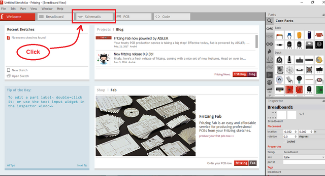
To begin, open your Fritzing beta software and click "Schematic" to open its schematic viewer.
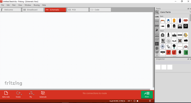
And this is the schematic viewer
Step 2 | Placing of Components
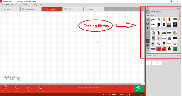
To place, find the library in the Fritzing located in the upper right section.
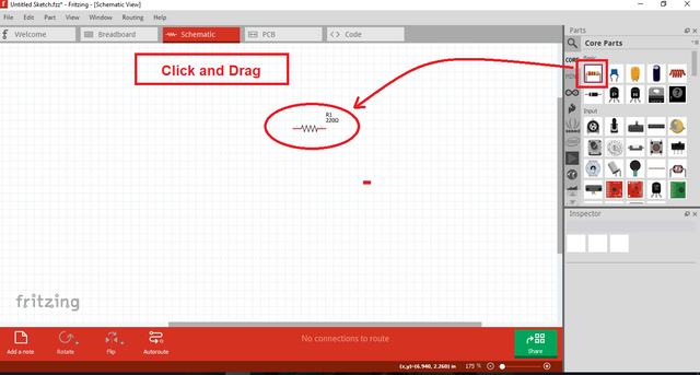
Click the selected component and drag it to the workstation.
To fully understand and for users to catch up, we will place the components by stages (transformer, rectifier, filter, regulator, and load)
Step 3 | Place transformer
Search the transformer in the library and place it to our schematic workstation. Refer the procedure in step 2 for placing components.
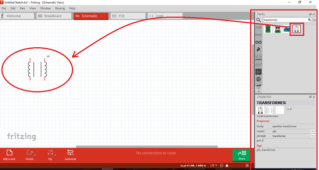
Step 4 | Place Rectifier
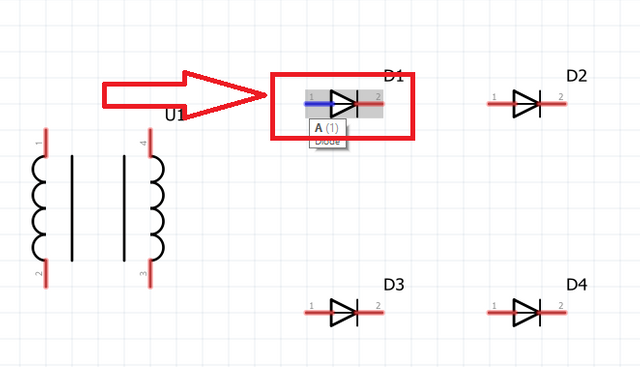
Our rectifier used here is a bridge rectifier. We need to place four diode for the rectifier.
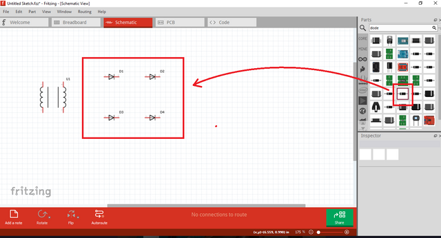
Step 5 | Place Filter
We can use capacitor as a filter for this circuit. For this, we will use 100 uF and 1 uF electrolytic capacitors.
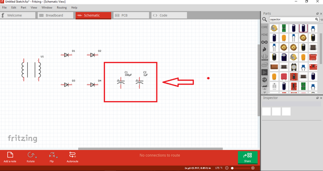
Step 6 | Place Regulator and Load
For the regulator, we will use LM317 IC because its regulated output is variable. Our power supply will have a multiple DC voltage output. For the load, we will use a resistor.
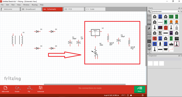
For the additional components, here are the explanation;
Potentiometer - used to vary regulation
Capacitor - additional filter after regulation
Step 7 | Wiring the schematic
Wiring in Fritzing beta is not complex like other software. We will locate the component to wire using the mouse pointer and wait for the component pin to become color blue. After that, click the pin, drag your mouse and click again where you want to connect.
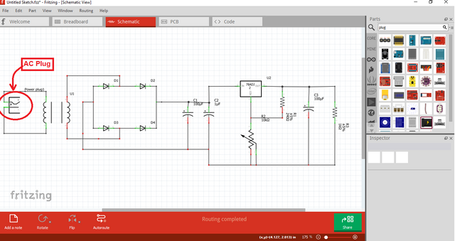
Here is our finish schematic diagram
Part B | Breadboard Prototyping
Step 1 | Open Breadboard Viewer
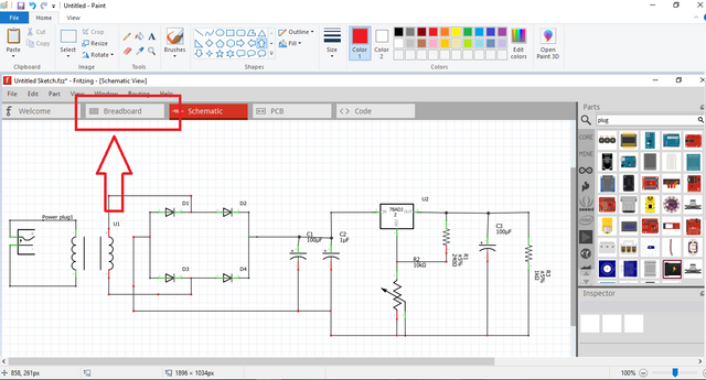
To start, click the breadboard button to open "Breadboard View"
This is what it look when we open the breadboard viewer.
Step 2 | Arrange Components
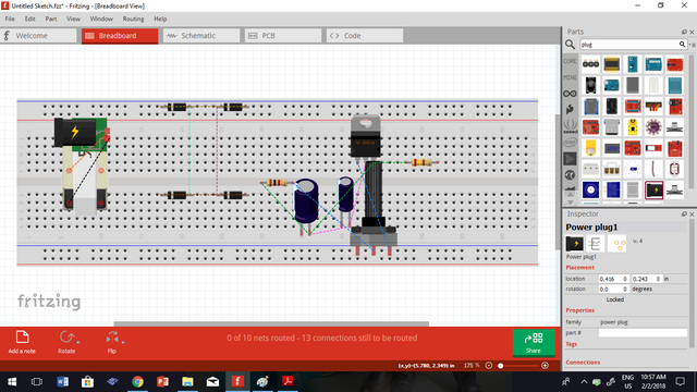
This time, it is all about your creativity how will you arrange your components. The dash lines represents the connection of components based on your drawn schematic.
To arrange, click and drag the components where you want to place. We can rotate the component by right clicking it. Rotating it will make your arrangement appropriate.
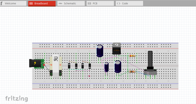
This is how I arrange my component. Well, you can arrange it too according to your likeness.
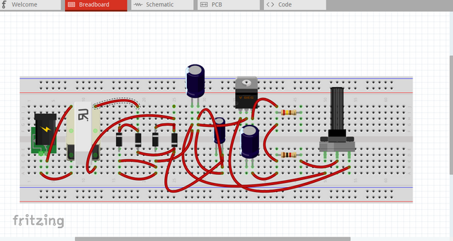
Step 3 | Wiring the Components
When wiring to breadboard, follow the dash lines. These lines are your clues on what components you will wire. Click the pin where you want to connect, drag the wire and release where it should be connected.
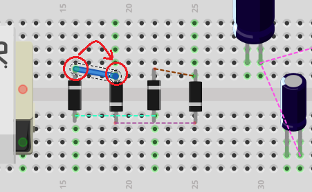
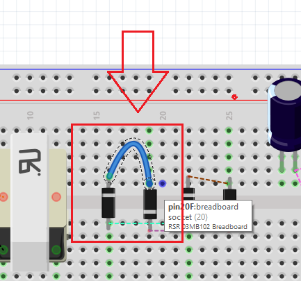
To make the wire curve that looks like a real wire, press + hold control key and click the wire, drag the wire to adjust the curvature.
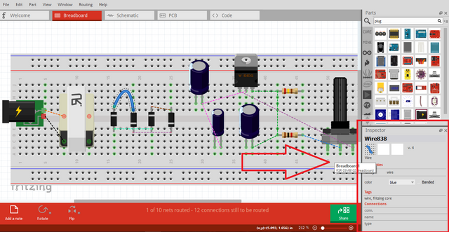
You can also change the color of wires if you are confuse with the connection. Just locate property box at bottom right of the screen and change the color.
Here is our final output of breadboard prototype.
Part C | Construction to Breadboard
Step 1 | Prepare components
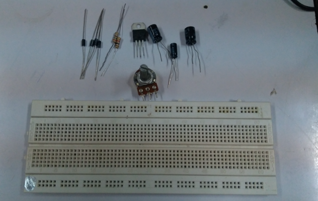
To start constructing the circuit, I suggest you should prepare first all the needed requirements.
Here are my needed components including breadboard.
Step 2 | Arrange the Components
My suggestion in arranging components is to arrange it by stages. Arrange first the rectifier, filter, regulator and then the load.
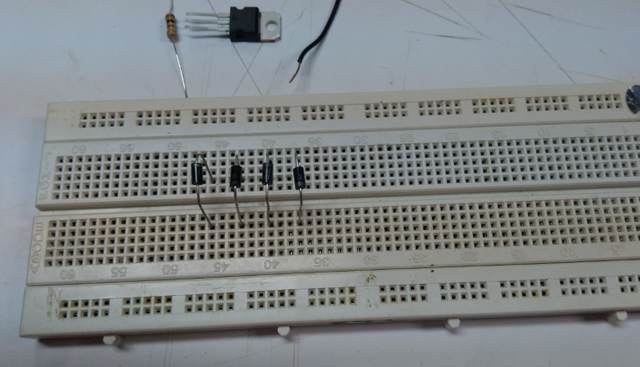
All components are now placed.
Step 3 | Wire the Components
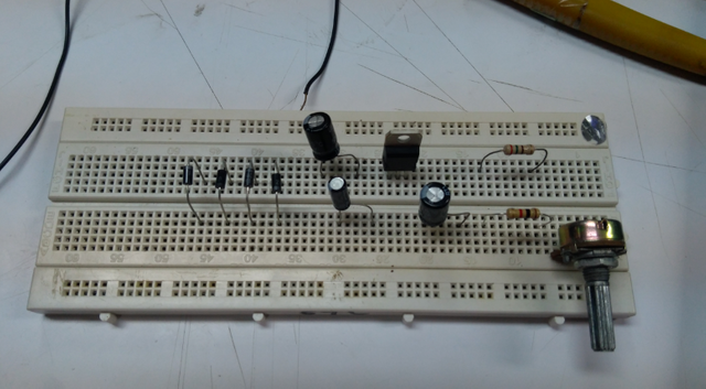
After placing and arranging the components, you can now start to wire the components. Use solid wire because it is easy to insert to our breadboard.
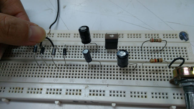
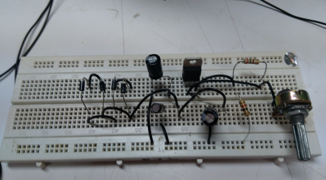
This our final circuit constructio and now it is ready for testing.
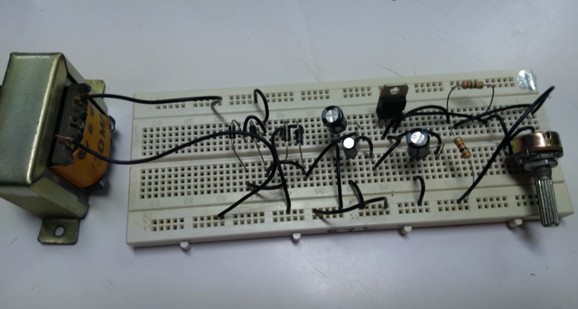
Testing and Results
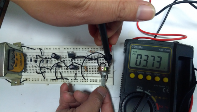
Our circuit now produces a regulated DC Voltage upon testing.
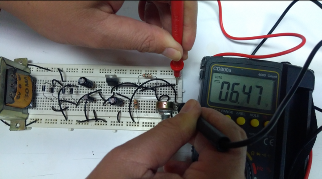
The output voltage varies as I turn the knob of potentiometer. Therefore, we created a variable output power supply.
Curriculum
Here are my other tutorial, you can check it out for reference. This could might help you.
Posted on Utopian.io - Rewarding Open Source Contributors
Thank you for the contribution. It has been approved.
You can contact us on Discord.
[utopian-moderator]
Downvoting a post can decrease pending rewards and make it less visible. Common reasons:
Submit
Thank you...
Downvoting a post can decrease pending rewards and make it less visible. Common reasons:
Submit
Hey @thinkingmind I am @utopian-io. I have just upvoted you!
Achievements
Suggestions
Get Noticed!
Community-Driven Witness!
I am the first and only Steem Community-Driven Witness. Participate on Discord. Lets GROW TOGETHER!
Up-vote this comment to grow my power and help Open Source contributions like this one. Want to chat? Join me on Discord https://discord.gg/Pc8HG9x
Downvoting a post can decrease pending rewards and make it less visible. Common reasons:
Submit
very good post for the development of hardware with Fritzing beta software. I invite you to review my post in https://steemit.com/utopian-io/@edagmi/qucs-simulator-for-semiconductor-electronic-circuits-introduction
Downvoting a post can decrease pending rewards and make it less visible. Common reasons:
Submit