What Will I Learn?
- Users will learn the analysis of thevenin circuit theorm
- Users will learn how to use and solve parameters of thevenin theorem.
- Users will learn how to simulate circuit to verify the result of thevenin theorem.
Requirements
For the users to follow, they will need the following;
- scientific calculator
- paper and pen
- pc or laptop
- QUCS circuit simulator (can be downloaded at https://sourceforge.net/projects/qucs/)
- basic knowledge in circuit analysis (parallel - series resistor, voltage calculation)
Difficulty
- Intermediate
Tutorial Contents
This tutorial is about analyzing the concept of a circuit theorem called Thevenin theorem. It shows when to use, how to use, and how to solve the circuit analysis using thevenin theorem. The last part of this tutorial shows how to verify thevenin theorem with the aid of a circuit simulator called QUCS. The results using mathematical approach will then be compared to the results using QUCS simulator and will evaluate base from the gathered data.
Concepts of Thevenin Theorem
Before we use this theorem, we should discuss first the basics concepts of this. This is for us to have a on-hand knowledge of this theorem.
It is common today to have a circuit systems that have a variable and fixed elements. These variable elements are can be the loads of our circuit and fixed elements are the core circuit itself. Load can be variable at times when there are multiple loads intended for the circuit. Example for this scenario is the power supply circuit. From the name itself, it is used to supply power to circuitry (usually in DC voltage). We can use this to supply a dc motor, electronic appliances, battery charger, DC voltage operated mechanism and any related devices.
Each time this load is changed or say variable elements are change, the entire circuit should be analyzed again to determined the electrical parameters delivered to the load (current, power, voltage, resistance). To avoid this to happen, a circuit theorem called thevenin is use for this analysis. This theorem provides a technique that the fixed elements circuit is replace with a equivalent circuit consisting of voltage source called thevenin voltage (VTh) and a fixed resistance called thevenin (RTh) resistance
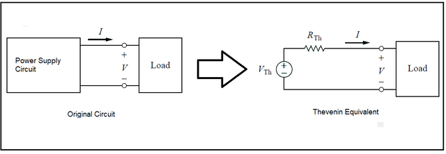
Thevenin theorem statement [by M. Leon Thevenin (1857–1926)]
states that a linear two-terminal circuit can be replaced by an equivalent circuit consisting of a voltage source VTh in series with a resistor RTh, where VTh is the open-circuit voltage at the terminals and RTh is the input or equivalent resistance at the terminals when the independent sources are turned off.
Steps on How to Convert Circuit to Thevenin Equivalent
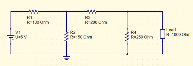
For the circuit, we will use this;
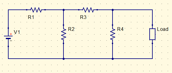
Step 1. Remove the load
Our aim is to have a thevenin equivalent for that circuit. So, we will remove the load to separate it from the circuit and leave the load section of the circuit open.
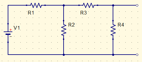
Step 2. Remove the voltage source and replace with short cicuit equivalent
Our next aim is to solve for the thevenin resistance (RTh). RTh is the input resistance seen at the open terminal of the load. So, we will remove the load and replace with short circuit equivalent to solve the input resistance or RTh.
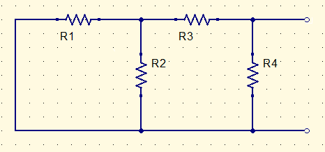
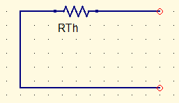
Step 3. Solve for RTh
To solve for the total resistance, we will use our knowledge in combining series and parallel resistors.
For this circuit, R1 and R2 is in parallel (R1||R2), the combination of R1 and R2 is series with R3 ( (R1||R2) + R3 ), this combination is again parallel to R4 ( [(R1||R2)+R3] || R4 ).
RTh = ( [(R1||R2)+R3] || R4 )
This is the result.
Step 4. Solve for VTh
VTh is the voltage seen at the open terminal of our load. Therefore, it is the same voltage with resistor R4 (VR4). We can use our background in basic circuit analysis like ohm's law, mesh, loop analysis to solve voltage in R4.
VTh = VR4
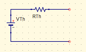
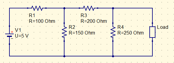
To use the concept of Thevenin theorem, we will give values to our circuit and solve.
This is the circuit;
By using the stated steps above, here is our simplified circuit to solve for RTh;
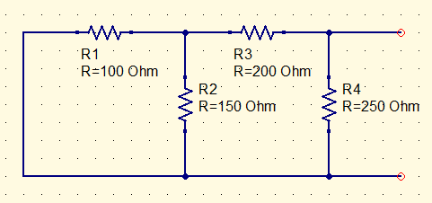
Solving for RTh:
RTh = ( [(R1||R2)+R3] || R4 )
R1||R2 = 100|| 150 = 60
[(R1||R2)+R3] = 60 +200 = 260
( [(R1||R2)+R3] || R4 ) = (260x250)/(260+250) = 127.45
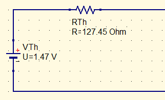
Therefore RTh = 127.45 ohms
Solving for VTh;
For this, we will use ohms law to solve the voltage. But, if you want other way of solving this the result would be the same.
Simplify first the circuit for ohms law,
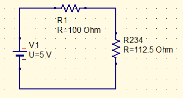
R234 = combination of resistor R2, R3 and R4
R234 = (R3+R4) + R2 = (250+200) || 150
R234 = 112.5
using voltage divider;
VR234 = [R234/(R234+R1)] x V
VR234 = [112.5/(112.5+100)] x 5
VR234 = 2.65 V
Now, the voltage of R234 will be our voltage source
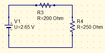
VR4 = [R4/(R3+R4)]xV
VR4 = [250/(200+250)] x 2.65
VR4 = 1.47
VR4 = VTh
VTh = 1.47 V
This will be our Thevenin equivalent
How to Use the Thevenin Equivalent?
Consider these two loads; Load1 and Load2
Load1 = 500 ohm
Load2 = 1000 ohm
Load1 scenario;

Our Thevenin Equivalent
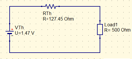
Let us calculate the voltage(VL) and current (IL) delivered to the load.
VL = [RL/(RL+RTh)]x VTh = [500/(500+127.45)]x 1.47
VL = 1.17 V
IL = VL / RL = 1.17/500
IL = 2.32 mA
Load2 scenario;
For the traditional analysis of this, we will back from beginning because the load resistance was change. But, Because of Thevenin we will not do that.
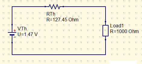
Let us calculate the voltage(VL) and current (IL) delivered to the load.
VL = [RL/(RL+RTh)]x VTh = [1000/(1000+127.45)]x 1.47
VL = 1.30 V
IL = VL / RL = 1.30/1000
IL = 1.30 mA
Verify using QUCS Simulator
Step 1. Open Qucs Simulator
Step 2. Place components
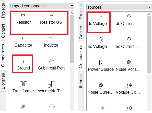
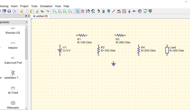
From the Component tab located at left window, select the components needed to perform. Click the component and click again to the canvas to place.
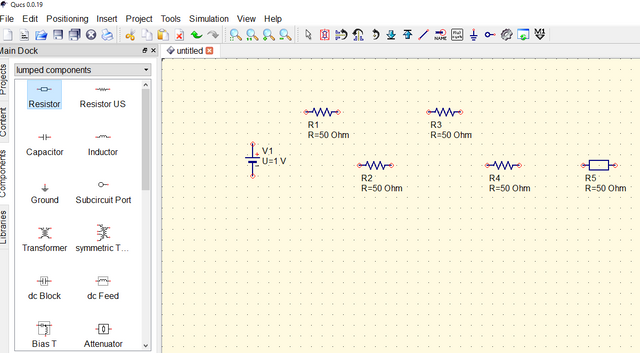
Step 3. Change Value and Arrange
Arrange the circuit to prepare for wiring. Right click the component to display menu like rotate and delete. Double click the component to change the values of components.
Step 4. Wire the circuit
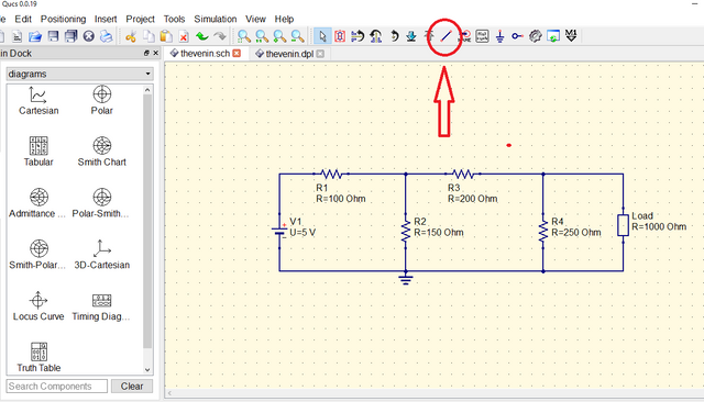
Click the wire icon in the toolbar to start wiring. Click the pin of component to initiate and end by click to another pin.
Step 5. Preparing for Simulation
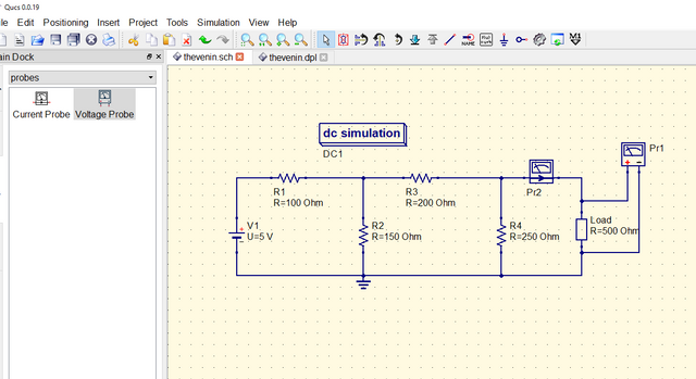
To prepare, place meter from components tab to measure the voltage and current upon simulation. Click what type of simulation from the simulation tab. I am using here a DC simulation because it only involves DC source.
Step 6. Start Simulation
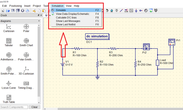
Before starting, save the file because it will not simulate if you don't save. Click the simulation button in the menu bar to simulate.
Step 7. Display Simulation Result
At simulation, a new canvas tab will appear to display our simulation results. We need to choose what type of tool to display the result. Here I am only using the Tabular tool to display the result.
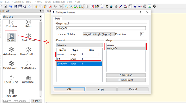
Here are the results.
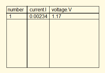
The Current and Voltage is the same in the mathematical approach in Load1 Scenario.
Change the Load to 1000 Ohm
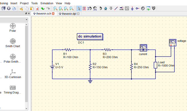
This is the simulation result
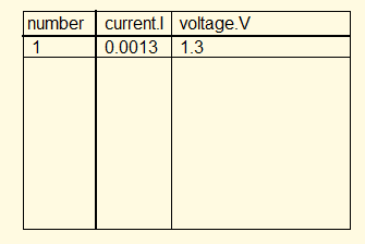
The Current and Voltage is the same in the mathematical approach in Load1 Scenario.
Summary
Based from the mathematical approach, thevenin theorem statement was verified and this theorem is true. We solve first the thevenin equivalent and we inserted two possible loads. In traditional circuit analysis, if we change the load we start all over again to solve for delivered voltage and current because the overall resistance was changed. By using thevenin theorem, solving for delivered voltage and current will be easier if the load was changed.
At the simulation using QUCS. It was verified by the aid of QUCS that thevenin theorem is true by comparing the result from mathematical approach and from simulation.
Curriculum
Here are my other tutorials, you can check it out for reference. These tutorials could might help you.
Posted on Utopian.io - Rewarding Open Source Contributors
Thank you for the contribution. It has been approved.
It was approved but please do not use irrelevant tags in your future tutorials. That may lead to rejection. I would also advise to use tags relevant to the post like, electronics, circuit instead of steemgigs, cebu.
You can contact us on Discord.
[utopian-moderator]
Downvoting a post can decrease pending rewards and make it less visible. Common reasons:
Submit
thank you.. yes, i'll do it next time
Downvoting a post can decrease pending rewards and make it less visible. Common reasons:
Submit
Hey @thinkingmind I am @utopian-io. I have just upvoted you!
Achievements
Suggestions
Get Noticed!
Community-Driven Witness!
I am the first and only Steem Community-Driven Witness. Participate on Discord. Lets GROW TOGETHER!
Up-vote this comment to grow my power and help Open Source contributions like this one. Want to chat? Join me on Discord https://discord.gg/Pc8HG9x
Downvoting a post can decrease pending rewards and make it less visible. Common reasons:
Submit
Nice post buddy, It was a very detailed discussion in fact these post will become one of the guide of my students to solve problems involving thevenin theorem. Wew upvoted!
Downvoting a post can decrease pending rewards and make it less visible. Common reasons:
Submit