Original creation date: 14th December 2018
Note: Originally I posted this on my Wordpress Blog (https://1337codersblog.wordpress.com), but I decided to switch to steemit, so I copied it from there.
Improved Marx Generator for high voltage applications
Currently I needed a generator capable for producing a high voltage pulse out of a voltage source with 15 Volt output. Because the voltage source can provide AC and DC voltage I could use circuits for both voltage types. After some search with Google I found 3 possible ways to achieve this goal:
- Using a step up converter. As I found out by simulating this base circuit it tends to become instable when it builds up its voltage to the desired level. The only way to fix this would be adding an active control loop which would decrease the pulse depending on the current output voltage. I decided that such circuit would be too complicated for my application.
- Using a high voltage cascade. This was a better one, but it turned out, that it only loads with one phase of its AC voltage supply. Later I found out that the Trimborn cascade solves this problem, but that circuit would take up too much space.
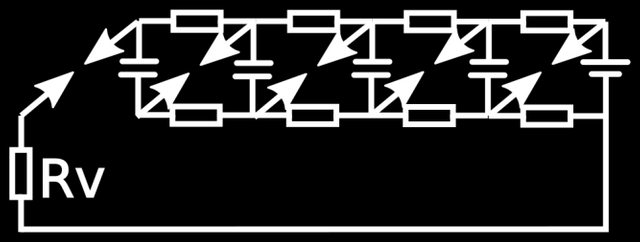
- Using an improved version of the Marx Generator. My tests in a circuit simulator showed, that this circuit was a good base for an implementation. A Marx Generator loads its capacitors in parallel until they are full. Then the spark gap gets triggered, which will wire all capacitors into one serial power line, which outputs a voltage being a multiple of the input voltage:

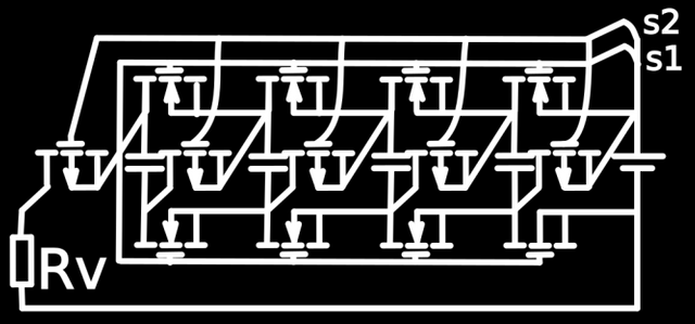
However the original Marx Generator has some problems. First, there is some unwanted backflow over the loading resistors between the capacitors which leads to a quick voltage drop on the voltage supplied to the consumer Rv. Second the spark gap is sensitive to environmental factors like humidity and temperature. To fix this problems I replaced the spark gaps against p-channel MOSFETs and the loading resistors against n-channel MOSFETs:

First, switch s1 is closed and switch s2 is closed. The n-channel MOSFETs are in enabled state, so the capacitors are getting charged. After charging the capacitors, s1 is opened so the n-channel MOSFETs are disabled. The loading circuit is deactivated now and the capacitors hold their charge. Then s2 is opened. Now the p-channel MOSFETs are enabled, the capacitors release their charge and Rv gets a high voltage pulse. The output voltage is in theory (n+1)*U0, where n is the amount of stages and U0 is the input voltage. The actual voltage will be lower, because the MOSFETs behave like resistors, so you should choose MOSFETS which maximum current is as high as possible, even if the actual output current is much lower.
I also tried to use this circuit for an unbreakable power supply, but as I found out, the input voltage in that special application was too low for the p-channel MOSFETs to enable. So when building this circuit, you should ensure that the input voltage is at least as high as the Gate-Source voltage needed to enable the p-channel MOSFETs.