I've decided to (destructively) tear down a radio transmitter that I've had sitting in a drawer for several months.
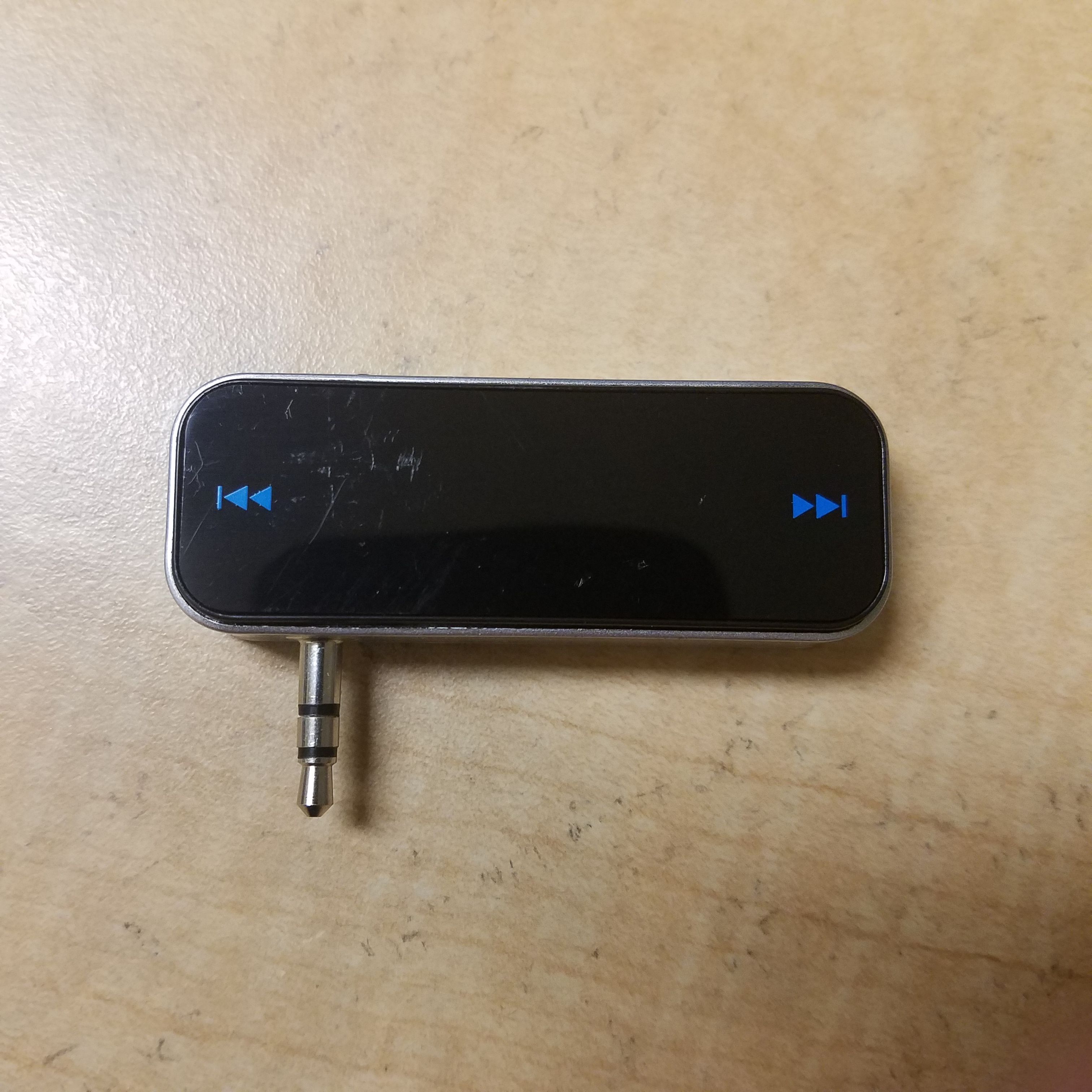
This device transmits on the FM radio band. You can plug it into a phone's headphone jack to transmit your music on ~100 MHz radio waves. These transmissions can be received on any FM receiver (car, handheld, cell phone, etc). The original point of these devices is to listen to music in older cars that don't have audio jacks or Bluetooth receivers.
I picked this one up on Ebay awhile back. It transmits a lot further than it is supposed to as mandated by the FCC (this thing can be heard at least 200 meters away on a quiet frequency). The device is battery powered, charges via microUSB, and lets you select any frequency on the FM band to send your music. This lets you pick a channel not being used and tune your car radio to it in order to listen in.
Teardown
Unfortunately the manufacturer either didn't want people getting into this device, or was just extremely cost sensitive. The device is one solid box, with no screws of any kind. This unfortunately made it very clear, very quickly that I was going to have to destroy the outside of the device in order to get inside. A necessary sacrifice, unfortunately.
I went in through the front panel, which consisted of a flat strip of plastic that could be pressed on each side to change the frequency. This was ripped off with a screwdriver. Underneath was another thicker plastic panel concealing the internal circuitry. A little more destruction later, I was able to pry off the second panel and expose the top of the circuit board. The panels were glued down and didn't come off without some cracking and bending.
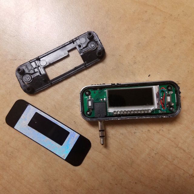
Unfortunately, all we can see are the two frequency adjustment buttons and the big liquid-crystal display. There's a switch on top that turns on the device. With the front panel off, it is very easy to see the backlit LCD:
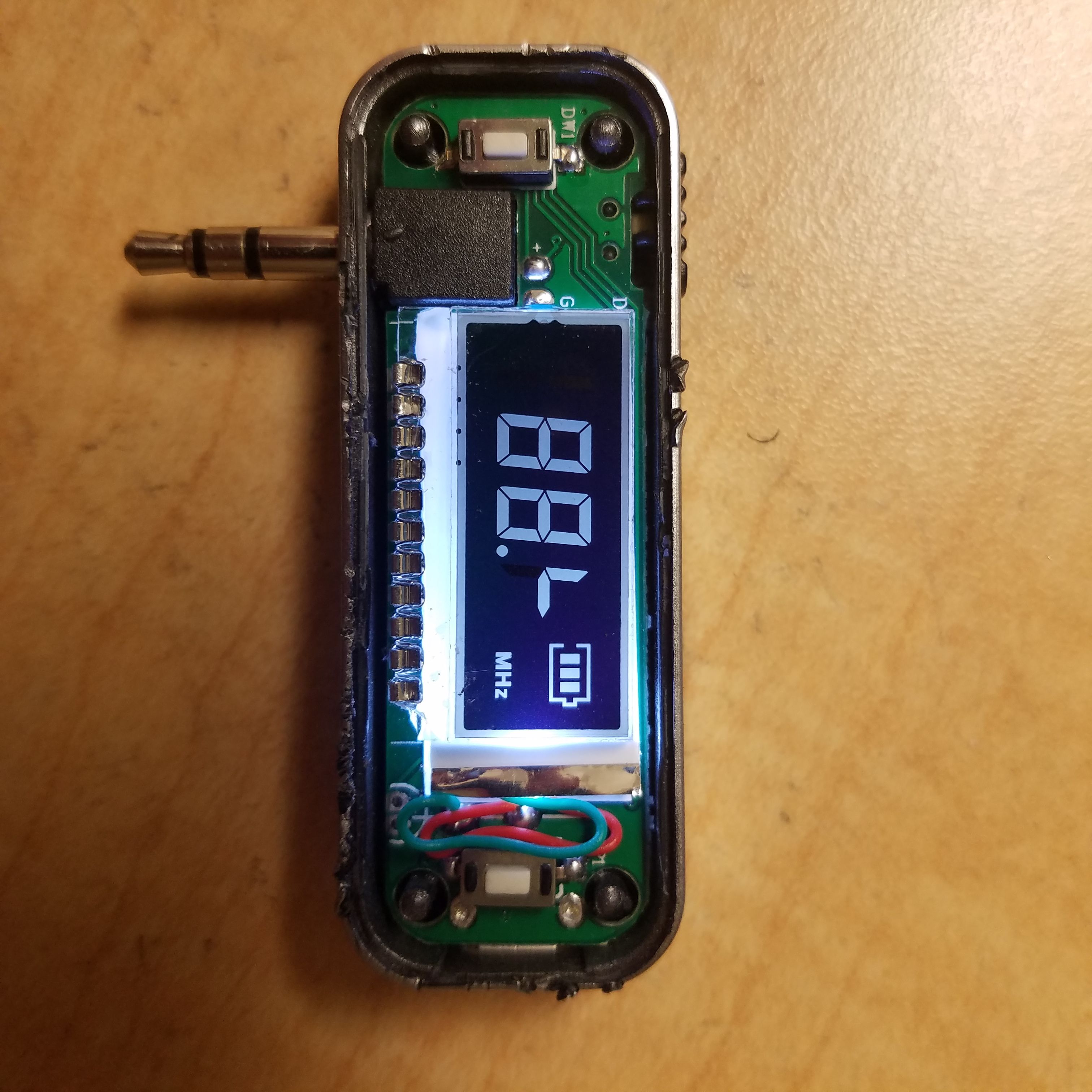
The audio jack makes it impossible to remove the PCB from this side, so I went and tried the back. Once again, there's a big plastic panel, so I destructively removed it with a screwdriver. This took a bit of prying, but eventually it came off to remove yet another plastic panel.
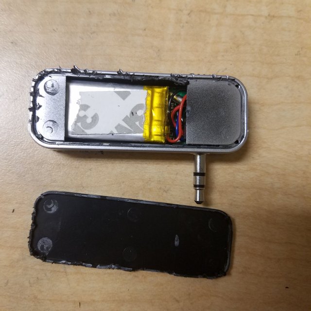
Here we can see a small lithium-polymer battery with kapton tape on top. This battery powers the device when it's not plugged in, and has good energy storage for its size. To see the rest, I removed that last plastic panel and cut out the glue sticking the audio jack to the frame to reveal:
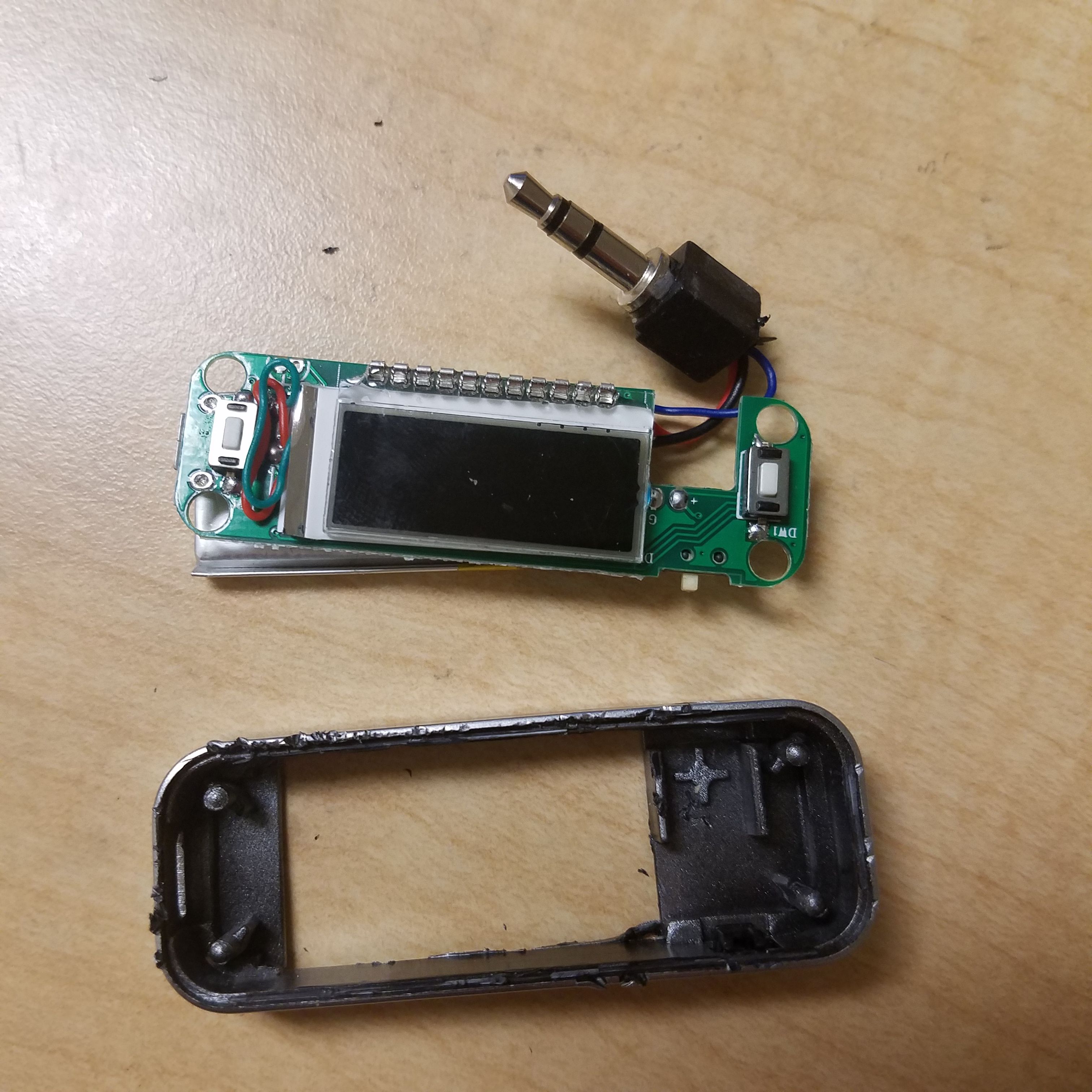
Unfortunately the removal of this board has made the frame totally useless, so in the trash it goes. But, we can now see the circuit itself! Here's a flipped-over view:
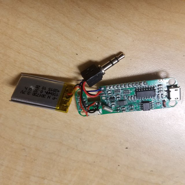
We can now clearly see the device. The PCB is mostly surface mount components. If you look closesly, you can see two tiny white rectangles on the left side of the board. These are surface-mount inductor coils, and likely serve as part of the transmitter as a filter or oscillator (or both). Also take note of the battery capacity: 0.37 W*hr. This means that the battery can put out around 1/3 of a watt for about an hour. This is 15-30x less capacity than a phone battery, for perspective.
The board has to serve two main functions: Charge/discharge the battery safely from USB voltage, and transmit/modulate the output radio wave.
The metal canister on the bottom of the board is, as usual, a crystal oscillator. This device lets the circuit maintain a very precise frequency, and probably helps it select which channel/frequency to broadcast on.
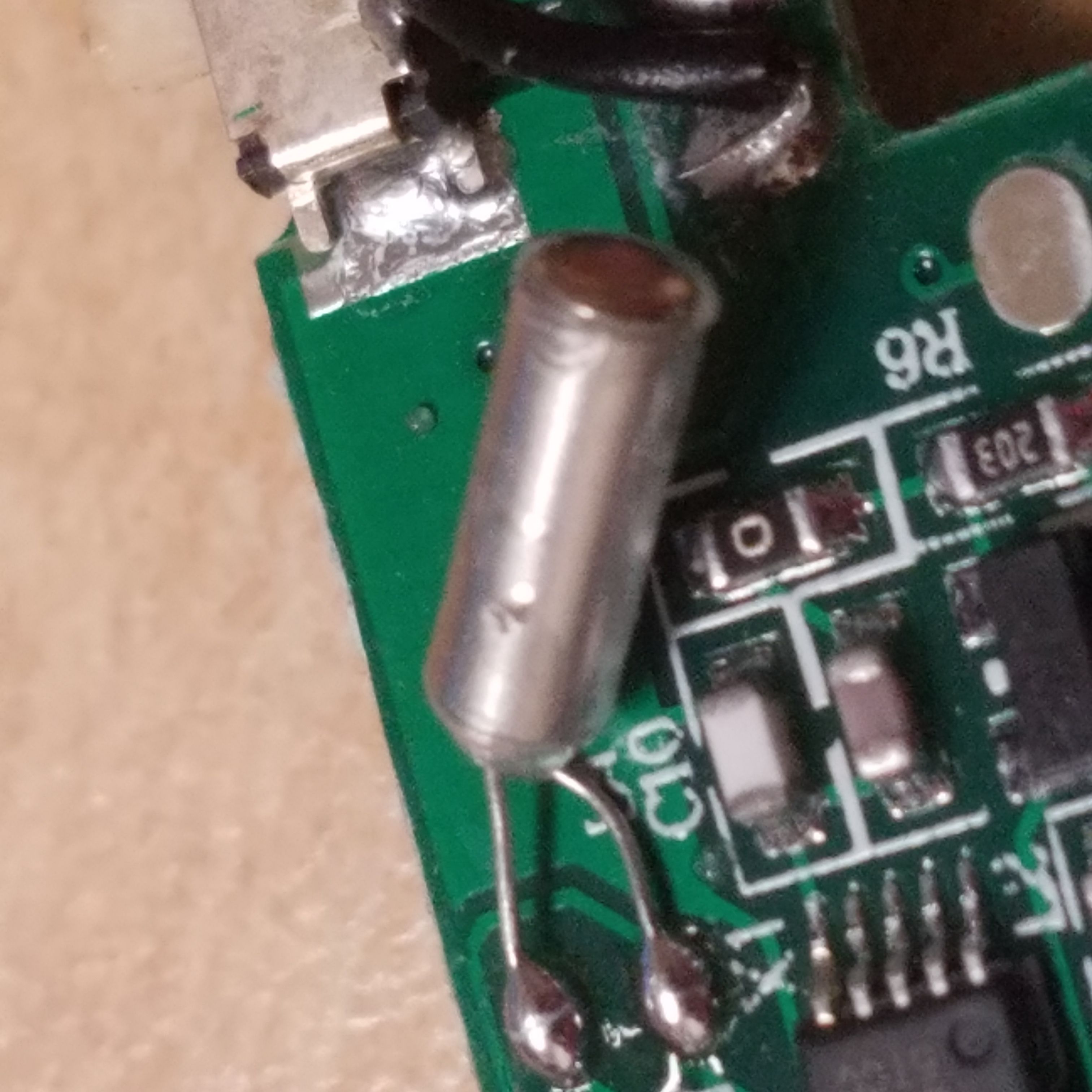
Also note the white inductor and brown capacitor, forming what is probably part of a filter, next door
Sadly, the board isn't really meant to be reverse engineered. The biggest IC on the board, the large black one, doesn't even have a name (it was either removed or just never even included one). The others have cryptic strings of numbers and letters printed on them that don't lead me to any datasheets, so I have no idea what they do. One of the smaller ones probably helps control the charging of the Lipo battery, though.
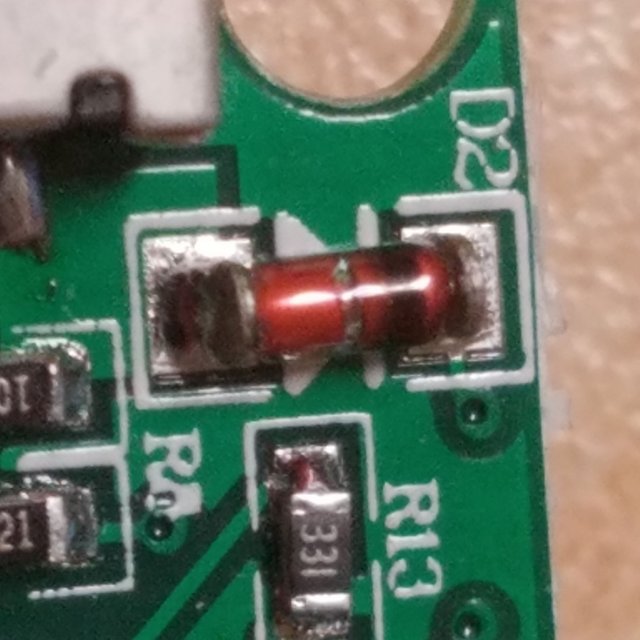
Without the ability to see what IC's are on the board, I've turned to investigating more basic components. Here we see a diode in a glass case, allowing us to see the inside. I measured the voltage drop to get 0.7 volts, which indicates that this is a Silicon diode (note that it's possible that the drop is inaccurate since I measured the diode without removing it from the board). Interestingly, due to the transparent case, this diode probably generates a tiny electric current in sunlight as light hits the internal PN junction, so it could potentially be used as the world's worst solar cell.
As you can see above, the remainder of the circuit is a cluster of surface-mount capacitors, resistor, and transistors. I found out that the backlight for the LCD (the light making it glow in the previous pictures) is coming from a line of white LEDs underneath the LCD. In order to avoid destroying the circuit itself, I didn't try to remove the LCD. However, we can see the light from the backlight coming through the PCB material, letting us see where the LEDs are:
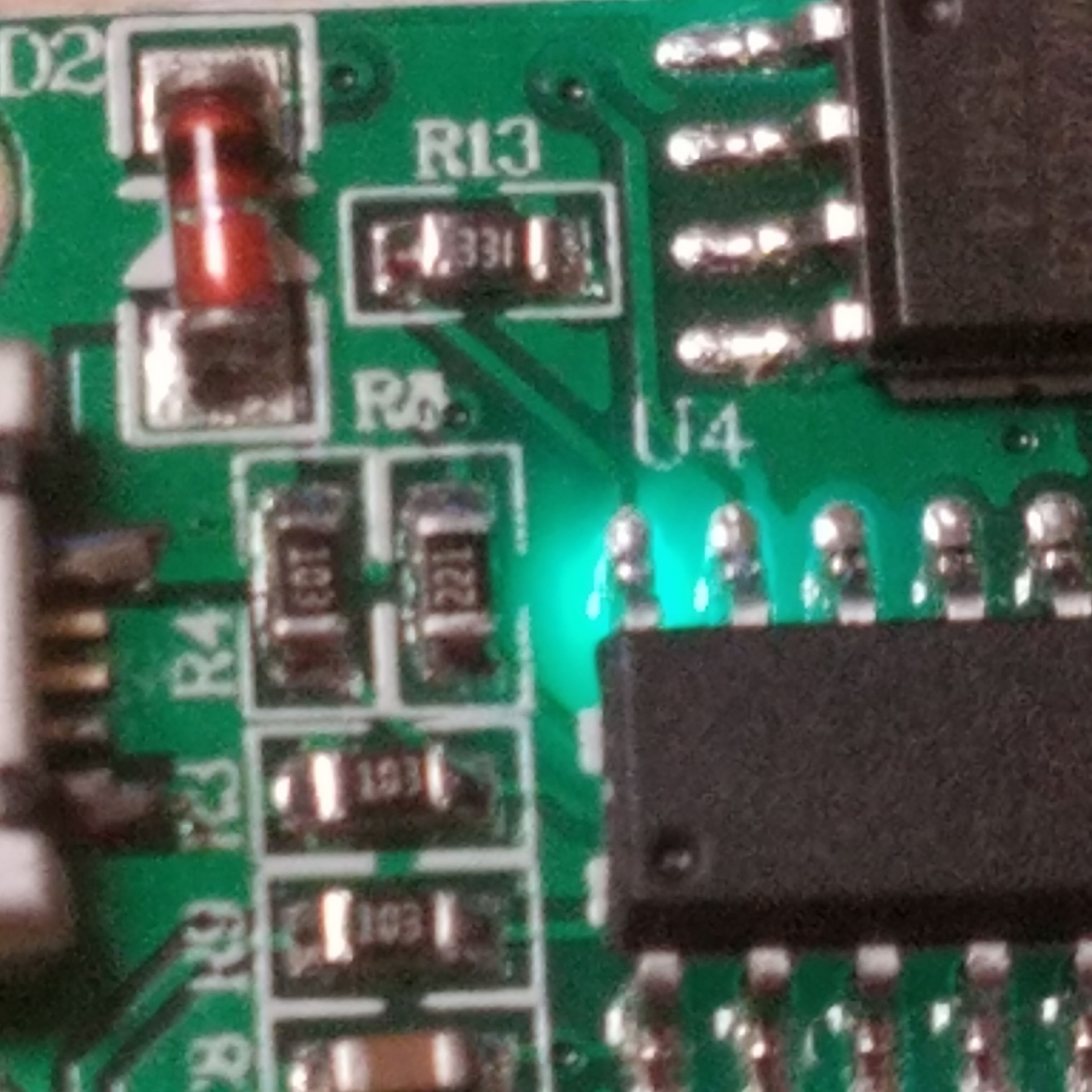
The glow above the IC-with-no-name is from the LCD backlights. Without these lights, you wouldn't be able to see the screen through the somewhat opaque front panel.
Curiously, I was unable to find an antenna. There isn't a PCB trace or wire that seems to look anything like one. Many times cell phones will use the headphone cable as a FM antenna, so it's quite possible (and my best guess) that the short cables attaching the audio jack to the circuit board are being used as a transmitting antenna for the FM signal.
Conclusion
You could technically use one of these devices to create your own semi-illegal, extremely short range radio station by attaching a microphone to the audio jack. This would send your voice over the air to any FM radio. I have a similar device that I bought at a local dollar store with much less range (well within the FCC limit, which I think is 50 feet for unlicensed FM transmitters). Since this one is made in China with no care for US regulations, it naturally blatantly violates that FCC limit. But, to be fair, nobody is going to care if you were to use one of these for your car and it went over 50 feet, since it is too weak to actually significantly interfere with strong stations.
I hope you learned something or at least found this post interesting. Please let me know if you have questions, comments, or corrections.
Thanks for reading!
All images in this post are my own. You are welcome to use them with credit.
Being A SteemStem Member
Downvoting a post can decrease pending rewards and make it less visible. Common reasons:
Submit
I like the way you took your time to explore the components of the device. I think the numbers were absent on the components because the manufacturer didn't want to reveal them. I think i would try get one for myself and check how it would work here in my country.
Interesting post
Downvoting a post can decrease pending rewards and make it less visible. Common reasons:
Submit
They're only a couple dollars on Ebay with free shipping if you'd like to try one out. I've even seen them for less than a dollar at stores but it's rare.
It's very possible that the manufacturer doesn't want anyone copying their somewhat involved design, and chose to remove the labels or use unlabeled ones.
Downvoting a post can decrease pending rewards and make it less visible. Common reasons:
Submit
I would definitely check it out online.
Exactly my thoughts too. But i never knew chineese manufacturers care about that.
Good morning
Downvoting a post can decrease pending rewards and make it less visible. Common reasons:
Submit
Whoa! Hey man, I never thanked you for the re-steem awhile back. I actually just noticed this. I wish Steemit had notifications. Anyway, thanks for re-steem and the follow. I followed you back. I love tinkering with electronics and other gadgets!
Downvoting a post can decrease pending rewards and make it less visible. Common reasons:
Submit
I would guess that it uses a chip antenna. They're actually stronger than PCB antennas these days.
Downvoting a post can decrease pending rewards and make it less visible. Common reasons:
Submit