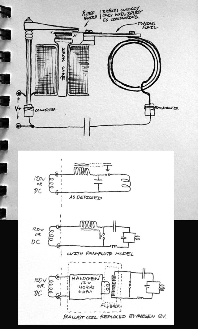
oooh, good point, I never really came across anyones documentation on the carbonizing of oil. Im curious what would be the minimum requirement for this to not be a problem. I had some thoughts earlier on mixing Tesla's flat disc viscosity turbine with the rotary spark gap to create some motion in the oil, but then I lost some heart with the complexities of controlling a motor and all its moving parts alongside the complexities of timing and whatnot. Really can't beat the simplicity of a multi spark-gap!
Upon your note of the resonant charging circuit and seeing how simplistic Tesla's circuit evolution descriptions were, I am very interested in hearing more about your expensive lessons on resonant charging! I would love to do away with heavy iron in these desktop designs. Another trademark testament to the importance of understanding "tuning"!
I caused some good curiosity with my Grandpa this Thanksgiving when showing him my illustration work on Teslas 1981 lecture (that you and I have talked about earlier this year), and he asked me if I could build him a high frequency oscillator for his office. I would love to send him something that doesn't require 20lbs of iron and oil for powerful and beautiful operation :D as for my office as well. Yes!
I'll do a post on resonant charging then, later.
Perhaps for your Grandpa's oscillator it could save a lot of iron if you start out with a high frequency transformer such as is often used with halogen lighting. What they do is, the first create an AC of about 40 KHz and then they use a small step-down transformer to get 12V. This 40 KHz AC will make resonant charging a lot easier (read: less iron required, compact design)
Downvoting a post can decrease pending rewards and make it less visible. Common reasons:
Submit
oh my gosh:
http://www.loneoceans.com/labs/flyback/
How surpassingly simple! :s I love the doing away with the 12v monster DC supply. Now this is what I am talking about!
Makes resonant charging easier? Im ready for the next installment! :)
Downvoting a post can decrease pending rewards and make it less visible. Common reasons:
Submit
You found LoneOceans! Look at his QCW... I tried to contact him, but he does not respond :(
But... erhm... yeah, a flyback circuit is very easy, as is a Slayer Exciter Coil (SEC). Look it up if you are looking for a simple HV source.
Downvoting a post can decrease pending rewards and make it less visible. Common reasons:
Submit
Yea I built my fair share of those sec designs.. but when compared to a 12v 40khz source off of a 120vac supply cuts down on alot of junk to package.
But im also having a desire to stick to the original desktop ideas that were perfected at maximizing the action at the terminals. This probably also includes the need for a good spark-gap for the quickest transients to reproduce the illuminating parallel wire experiments (transistors may not be as quick for efficiency sake).
The hallogen transformer + a flyback circuit sounds like it can compact the Blast part of this design. Leaving the spark-gap up for exploration still.
I remember your QCW plasma forming 'swords' topic... I also would like to hear another installment on that again :p
Downvoting a post can decrease pending rewards and make it less visible. Common reasons:
Submit
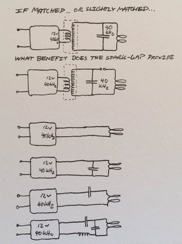
I included a sketch of the considered options. It seems that if the driving frequency is closer to the required primary frequency (in the case of a 40kHz Halogen ballast) the pan-flute addition would be unnecessary.

And then I guess it doesn't matter how fast the discharge is if resonant circuits are tuned properly. The critical property of the discharge is to not be so slow as to conduct in the wrong direction.
Interestingly enough I just found out that those 12v halogen ballasts have a halfwave envelope. Not exactly CW.

Downvoting a post can decrease pending rewards and make it less visible. Common reasons:
Submit