I'm getting a bit addicted to writing posts about breaking into electronics, so here's a break down of my beat up AM/FM radio receiver. I purchased it at a local Radio Shack that was going out of business sometime last winter. I've used it extensively to test various devices like my spark-gap transmitter experiment.
In this post I hope to go over what's inside this device and provide some insight into how it works.
Before we begin, recall that AM stands for "Amplification Modulation" and FM stands for "Frequency Modulation". In simple terms, AM radio stores sound in the 'height' of the radio waves, while FM radio stores sound in the 'spacing' between subsequent electromagnetic waves. Both methods are used to transmit information over the air, with AM radio broadcasts taking place using EM waves around 1 MHz in frequency and FM radio broadcasts using EM waves around 100 MHz in frequency.
What does this device do?
Like the radio in a car, it simply receives radio signals from nearby transmitter stations. These seem to be becoming less common, but I like having one to occasionally listen to radio or to have in emergencies. This radio is a combination AM/FM device, allowing the user to listen into either band.
The outside of my device is somewhat scratched due to weeks at the bottom of my overloaded backpack. There's quite a bit on the outside: A frequency monitor, a large speaker grill, a battery slot (takes 2 AAs for a total of 3 Volts input), tuning and volume knobs, a 3.5mm headphone jack port (this along with the lack of carrier-locked FM radio makes this radio slightly more useful than certain cell phones), and an extendable metal antenna about a foot long. The antenna is necessary to listen to longer-wave AM broadcasts but really doesn't need to be used for FM. This is because the electrmagnetic waves used in AM broadcasts have much longer wavelengths: Using the relationship c = f*L, the wavelength for 1 MHz AM radio waves comes in at about 300 meters!
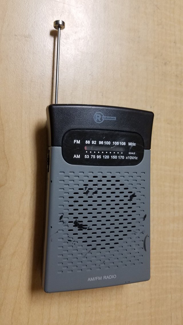
The batteries last quite a while and the speaker can get somewhat loud. It doesn't do too well at picking in AM signals in my mostly metal apartment building (as expected) but clearly receives FM audio. It can also be used to pick up lower frequency electromagnetic radiation produced by spark-gap high voltage experiments like the mini-stungun I made (which silences the AM receivers at close range without any antenna, indicating transmission of electromagnetic radiation).
Opening up the radio
Happily the device is somewhat easy to open. Two non-hidden screws (thanks Radio Shack!) on the back can be quickly removed. The plastic shell then needs to be harmlessly popped open with a small flat-head screwdriver, which is pretty standard procedure for stuff like this. Then, the entire thing pops open without too much hassle:
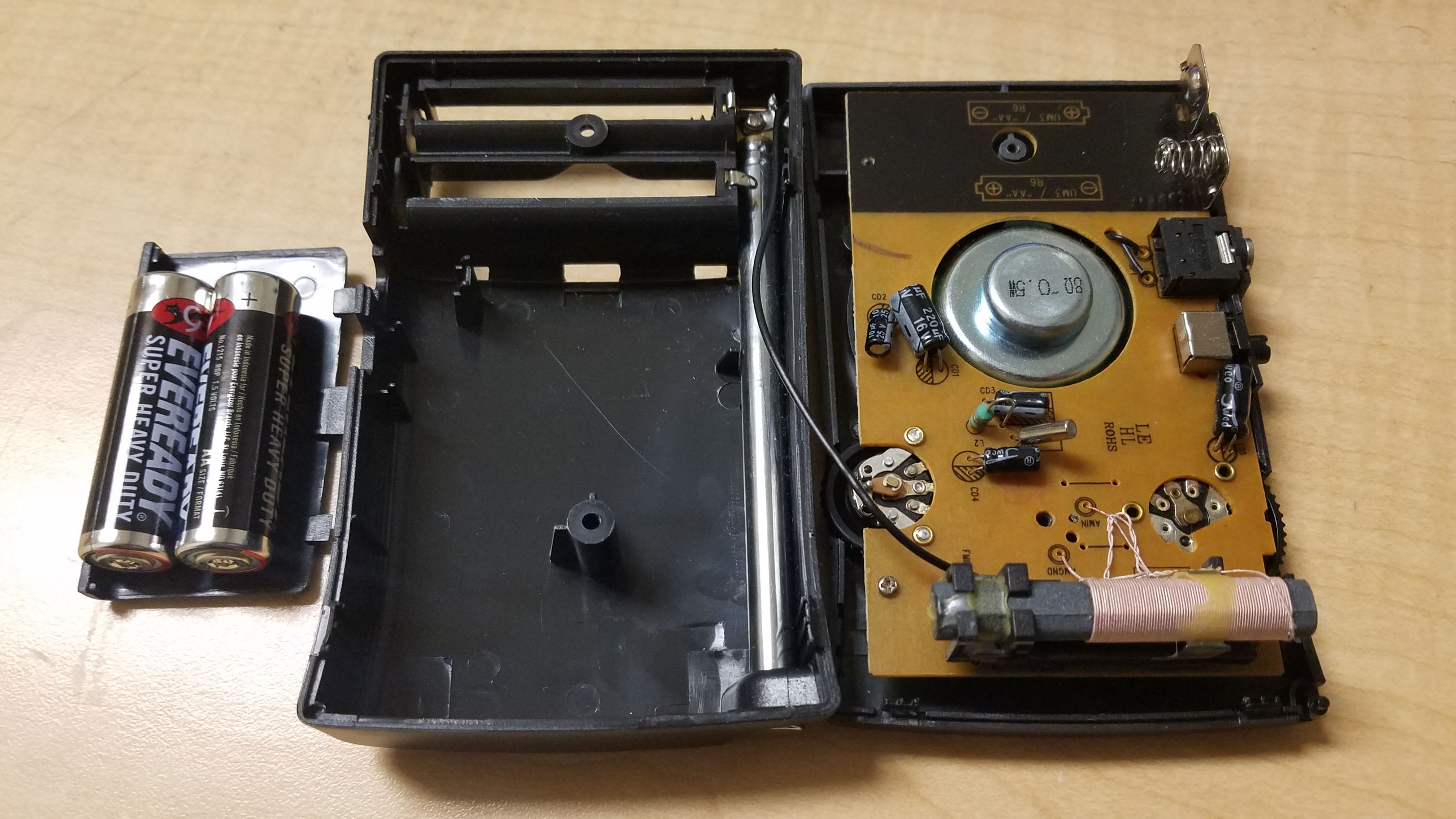
As you can see, the only parts in the backplate of the radio are the collapsed metallic antenna and the battery holder. All of the good stuff is on the front panel of the radio, containing all of the receiving electronics.
To begin, let's take a closer look at the biggest part on this board. I'm talking about the large pink and black coil at the top of the board. Here's a close-up image:
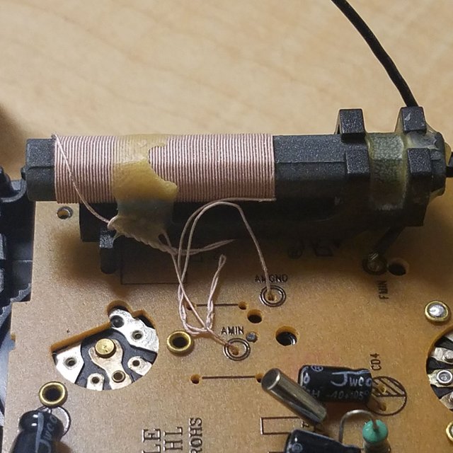
What we're looking at here is a large coil of wire surrounding a magnetizable core. This makes the device an inductor, or electromagnet. Inductors have some interesting properties due to them storing energy in a central magnetic field when powered up. In this case, it appears to form part of a LC oscillator circuit (a capacitor and inductor in parallel), which can be used in a radio receiver to filter out unwanted signals. Large coils like this in a radio receiver are typically indicative of the AM-receiving portion of the circuit. This is confirmed by the labels at the ends of the coil: AMIN and AMGND (AM-in and AM-ground).
Also on the front appears to be a crystal oscillator canister. Here's a closer look:
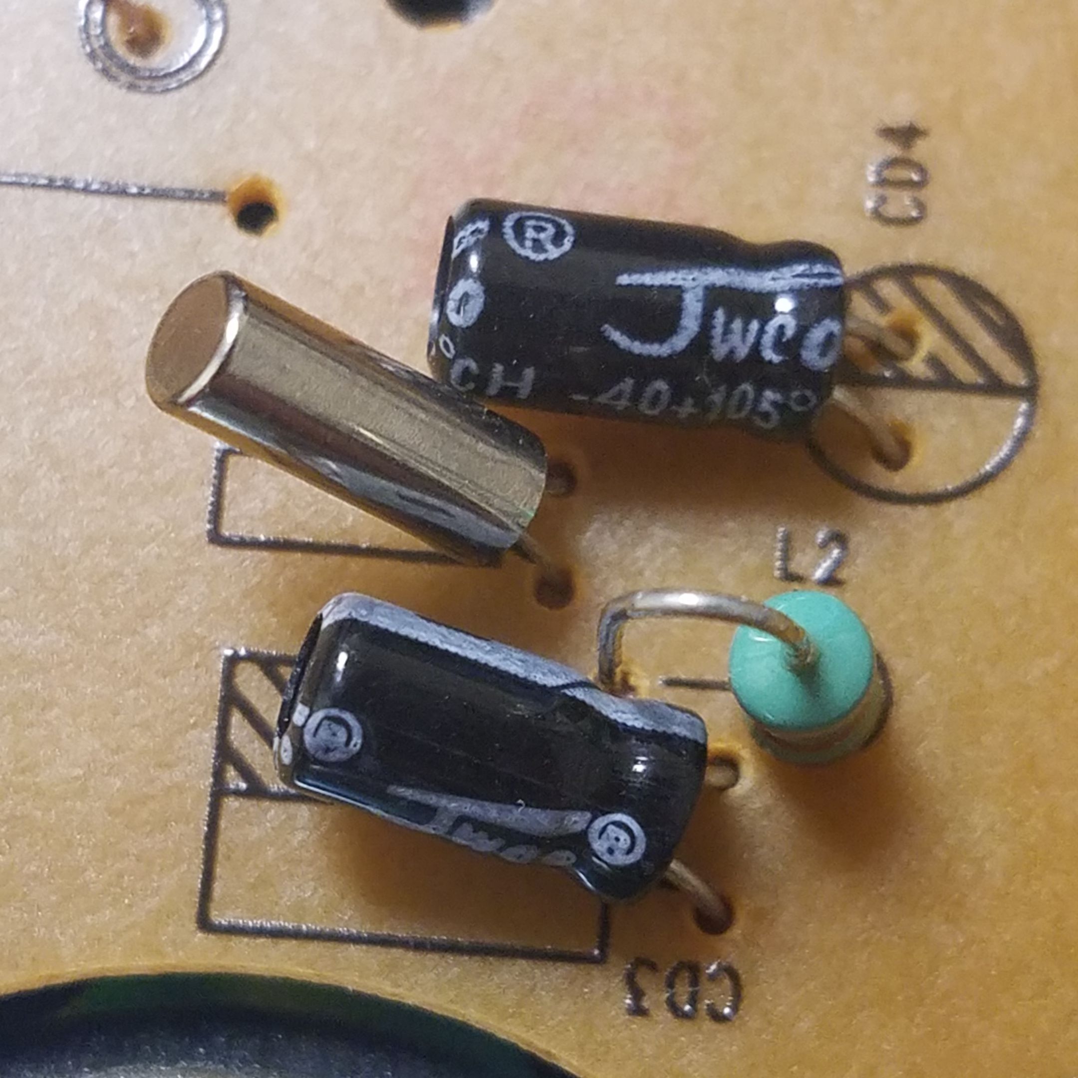
The very shiny canister is the oscillator crystal. The other canisters are electrolytic capacitors, and the green resistor-looking device is a small inductor.
This cylinder contains a piezoelectric crystal. Piezoelectric materials deform when you apply a voltage to them. Apply an oscillating voltage (AC or alternating current) to one and it will vibrate. Crystals like this have a very particular 'resonant frequency', usually in the megahertz range. This makes them useful for precise timing, and these are using in clocks as quartz oscillators. Here, I assume it's used as some sort of filter as well but I'm not completely sure.
Moving on to the back of the PCB requires removing two more easy to get to screws (it's always nice when the manufacturer makes a device easy to take apart). The back of the board has many, many more surface mount components:
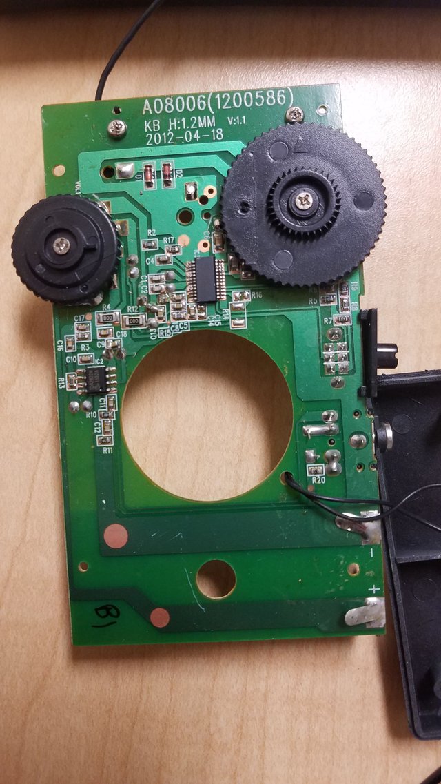
The first thing visible are the two black knobs. To avoid breaking how they interact with the gear-fed mechanism that moves the frequency display, I didn't unscrew the black plastic gears. Both of these are potentiometers (adjustable resistor) or variable capacitors (adjustable capacitor).
I have strong reason to believe the larger frequency-selector tuning knob is a variable capacitor while the volume knob is a potentiometer. If the tuning knob was a variable capacitor, it would fit with other tunable radios I've seen, as this would allow the user to change the capacitance of the capacitor in the LC oscillator filter portion of the receiver. This is backed up by the fact that the PCB traces guide one end of the AM receiver inductor coil into the tuning knob. If this is a variable capacitor, then turning the knob changes the capacitance of the capacitor, thereby changing the resonant frequency of the LC circuit and changing what radio frequency is picked up by the receiver.
Interestingly, this feature makes old radios (say an alarm clock from a thrift store) the single best place to salvage old variable capacitors, if you ever need one for something.
As a side note, I noticed the manufacture date was stamped on the top of this portion of the board. April 2012 is about 5 years before I bought the device so this thing has been around for awhile.
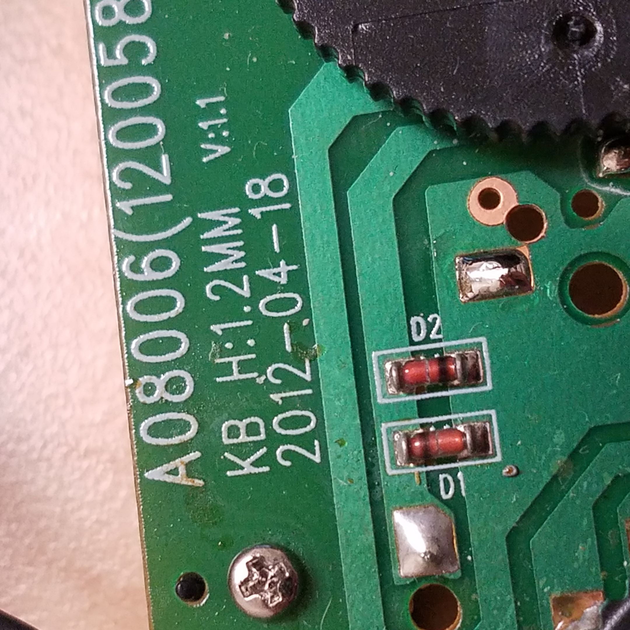
April 18th, 2012. Also visible are two Germanium (?) rectifier diodes in clear glass casings.
The rest of the components on the board are dedicated to boosting the signal received from the radio waves to a usable level. While you can directly listen to the radio using only the energy already present in the incoming radio waves (this is what old crystal radios do, and is why they don't need batteries to operate), this will only work very close to the radio source and will produce very quiet audio. Instead, why not amplify the incoming signal and run it through a higher power speaker using power from the onboard batteries?
Lots of surface-mount resistors and capacitors along with several ICs and the through-hole parts on the other side of the board do the job here.
The biggest IC on the board is this little guy, which I have identified as a cheap (~$2) RF receiver chip. This device can receive signals from AM and FM transmissions in a tiny form factor. It's visible on the above picture, but I took a closer shot:
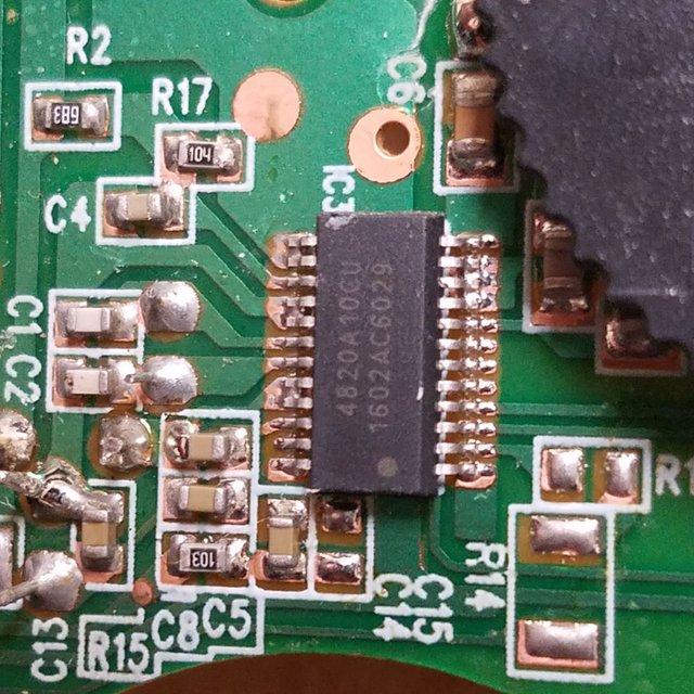
4820A10CU RF receiver surface-mount chip. I'm glad I don't have to solder this by hand.
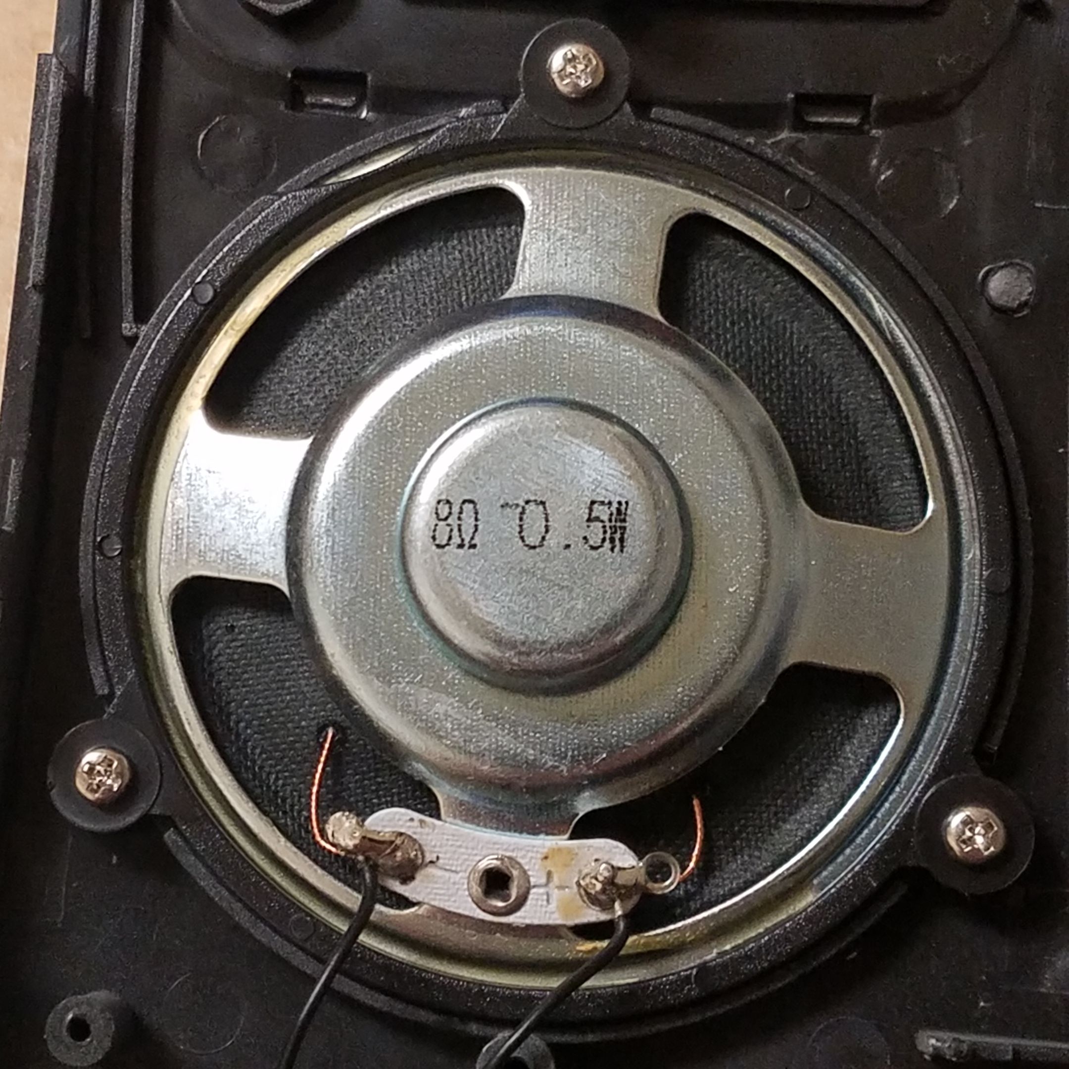
But what is a radio receiver without a speaker? Yes, you can technically just listen to broadcasts via the headphone jack port and some headphones, but a speaker is very convenient. Once the audio signal is extracted from the incoming radio wave and amplified, the signal is sent to a decent sized 8-ohm magnetic speaker (extra sound energy provided by the batteries). This speaker is hidden behind a solid plastic grill, but is easily visible with the back PCB removed. This speaker, like most speakers, works by running current through a coil of wire next to a large permanent magnet. When the coil is powered up, it is attracted to the magnet, vibrating the thin membrane and producing sound waves in the air for you to hear.
Conclusion
Since this device can't transmit (like the walkie-talkies I previously posted about), that's all there is on the circuit. I feel like I could have gotten a little more insight into its operation by removing the plastic knob gears, but doing so would have potentially damaged the device. I'm somewhat impressed by how simple it was to take apart this radio, and if something broke you could potentially replace the faulty component with few problems (although they didn't include a schematic, sadly, although this is not unexpected).
Let me know if you have any questions or comments, or if I said something that was incorrect. To facilitate discussion, I'll try to upvote all non-spam comments to the best of my ability.
Thanks for reading!
All images used in this post are my own. You are welcome to use them with credit.
Surprisingly I see so few hams here on steemit.
73 de LY1A
Downvoting a post can decrease pending rewards and make it less visible. Common reasons:
Submit
I have had my technician license for a few months now, typically just use it to talk on my campus repeater.
Downvoting a post can decrease pending rewards and make it less visible. Common reasons:
Submit
This is a test comment, notify @kryzsec on discord if there are any errors please.
Being A SteemStem Member
Downvoting a post can decrease pending rewards and make it less visible. Common reasons:
Submit
This is the first time i'm discovering the meaning of AM. Also i always thought AM and FM just worked on different frequencies, didnt know it was more than that.
Downvoting a post can decrease pending rewards and make it less visible. Common reasons:
Submit
Hey really nice post i wanted to ask like u said if u really dont need a voltage to get the fm signal that mean some radios without speakers just come with a pair of large amplifiers ?
Downvoting a post can decrease pending rewards and make it less visible. Common reasons:
Submit
I've seen some very cheap radios (one FM receiver from the dollar store, which I've only seen sold there once or I would have bought more) come without a speaker. The amplifier is still there, you just have to use a set of headphones and plug them into the radio to hear anything. The lack of speaker is just a way to save money.
Crystals radios on the other hand can produce sound from a speaker using only the energy in AM radio waves, so they don't need batteries. But the sound is extremely quiet.
Downvoting a post can decrease pending rewards and make it less visible. Common reasons:
Submit
Really nice article and easy to understand.
If you are related electronics i can suggest that you can use this device to make a wireless connection. It is so easy. Just connect the radio output (jack) to a standart point laser's anode and cathode instead of battery of the laser. You have a laser transmitter. If you send this laser any light detector which allows to collect the amplitude change from the radio, then with a simple circuit (amplifier) you can listen to the sound. According to the laser range you can send up this data for km in clear weather.
Thanks to remember such a beautiful thing...
Downvoting a post can decrease pending rewards and make it less visible. Common reasons:
Submit
@proteus-h I am a graduate computer engineer we had fm and am in our syllabus of digital signal processing my teacher were so weak that i did not understood anything about that but after your article I have learned a lot ........ Thanks for giving so much information keep it up bro #steemon
Downvoting a post can decrease pending rewards and make it less visible. Common reasons:
Submit
Si4820/24-A10 and one that you mentioned 4820A10CU RF receiver , are they same.? I actually don't have much idea about these datasheets
Downvoting a post can decrease pending rewards and make it less visible. Common reasons:
Submit
Yes, those two parts appear to be the same. I was able to even find a link to Digikey where you can buy these chips.
Downvoting a post can decrease pending rewards and make it less visible. Common reasons:
Submit