Here's a writeup of a simple radio-frequency energy harvester I built earlier this year. Now that I'm back at my apartment with my equipment I should be able to post more DIY projects. This device is crude, unoptimized, and imperfect ... but it works.
This super simple circuit converts radio waves collected into a crude wire antenna into electrical energy which is stored onboard two electrolytic capacitors. This is not a "free energy" device because it actually works: All of the energy brought into the capacitors comes directly from the energy of electromagnetic waves. You can build your very own harvester circuit with just 9 components and a piece of perfboard.
The actual amount of energy collected is absolutely tiny if you are only using ambient RF, so like most of my projects this is just a proof of concept. It's not going to charge a powerbank off of your cell phone emissions or anything like that ...
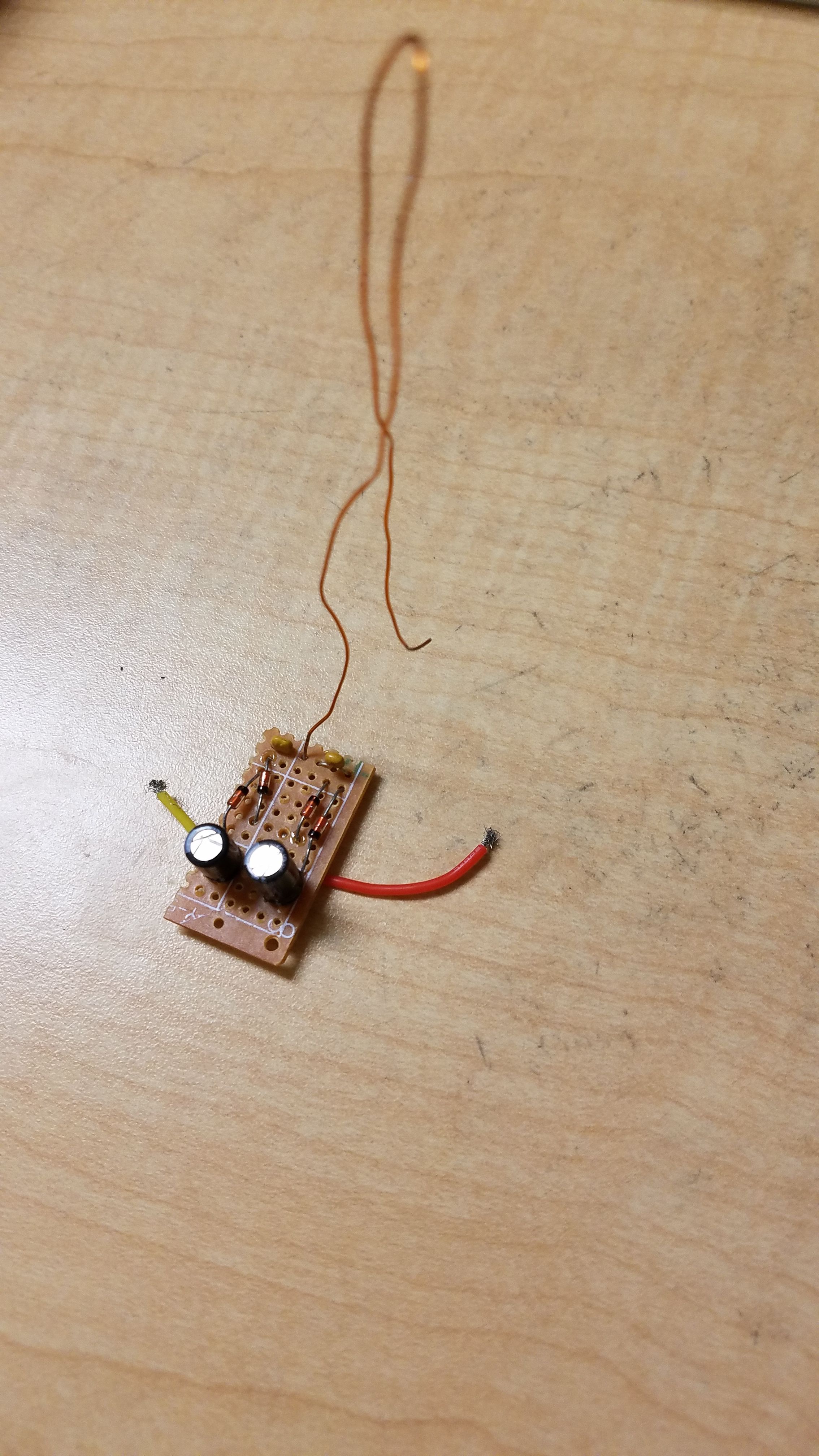
In case you don't want to get into the details, here's a picture of the completed crude harvester:

Operating Principles
Ambient electromagnetic radiation is all around you, harmlessly emitted from most electronics. Computers transmit 2.4 GHz microwaves for wifi/bluetooth and car FM transmitters transmit around 100 MHz to send audio to your car's radio receiver. Light itself is also, of course, electromagnetic radiation, but this device only works for much lower frequencies. I had the best luck around 100-200 MHz radiation. Electromagnetic radiation at these low frequencies (radio and microwave) is not ionizing and as such harmlessly passes through or is absorbed by your body.
EM radiation can be collected via antennas. Any radio receiver does this but only uses the captured radio wave energy to produce a detectable signal so that you can hear the broadcast. But these waves contain energy, and we can capture this energy and use it for other purposes, small as it may be.
Crystal radios, common starter DIY electronics projects, do just this. A crystal radio is a simple receiver that can be built from mostly scrap parts, and lets you listen to radio broadcasts without a battery. The crystal radio produces energy out of its piezoelectric speaker: Sound energy, that is. This energy has to come from somewhere, and in the crystal radio's case, it is harvested directly from the incoming electromagnetic radio waves.

A crystal radio receiver.
Image credit
Other devices, such as passive RFID tags, also work by extracting energy from electromagnetic fields.
This device works on the same principle: Extract useful energy from electromagnetic waves. Here's the schematic for the circuit (found by me online - I didn't design this, although it is pretty simple)
Capacitors C1 and C2 serve to isolate the antenna. The antenna in my case is made from a piece of copper wire soldered to the two capacitors. The wire is probably 20 centimeters long and was not optimized with any particular frequency in mind (this was a quick project). The four diodes form a full wave rectifier that converts the incoming alternating current produced by the inbound radio wave into direct current. Capacitors C3 and C4 then serve to store the harvested energy in an electric field - think of them as tiny batteries. For C3 and C4, I used 100 microfarad capacitors rated to 35 Volts. These are very small capacitors but will store enough energy to easily measure on my cheap multimeter.
Assembly
It's important to note that you can't just use any diodes for this and expect it to work. The diodes used need to be able to handle sufficiently high frequency and have a low voltage drop. To handle this task, I used the 1N34A Germanium diode (I got some on Ebay for a reasonable price). You can peruse the datasheet here. In particular, these diodes are used for FM radio detection - this is essentially the same thing the energy harvester circuit is doing, since it is rectifying an input signal close to the typical FM band in frequency. Note that although the datasheet states that the forward voltage drop is 1 volt, this drop is much lower at the low currents we are dealing with here.

1N34A Germanium Diode
Image credit
For assembly, I used a broken piece of perfboard I had lying around and a soldering iron to quickly connect all of the components. It is critical to get the polarity on the electrolytic capacitors correct. For the two capacitors connecting the antenna to the circuit, I used ceramic capacitors that don't need to be hooked up with a certain polarity. Once again, I used a badly optimized piece of wire as an "antenna" just to see if this would work. I unfortunately don't have the knowledge of RF theory yet to go much further, but the wire ended up working out just fine.
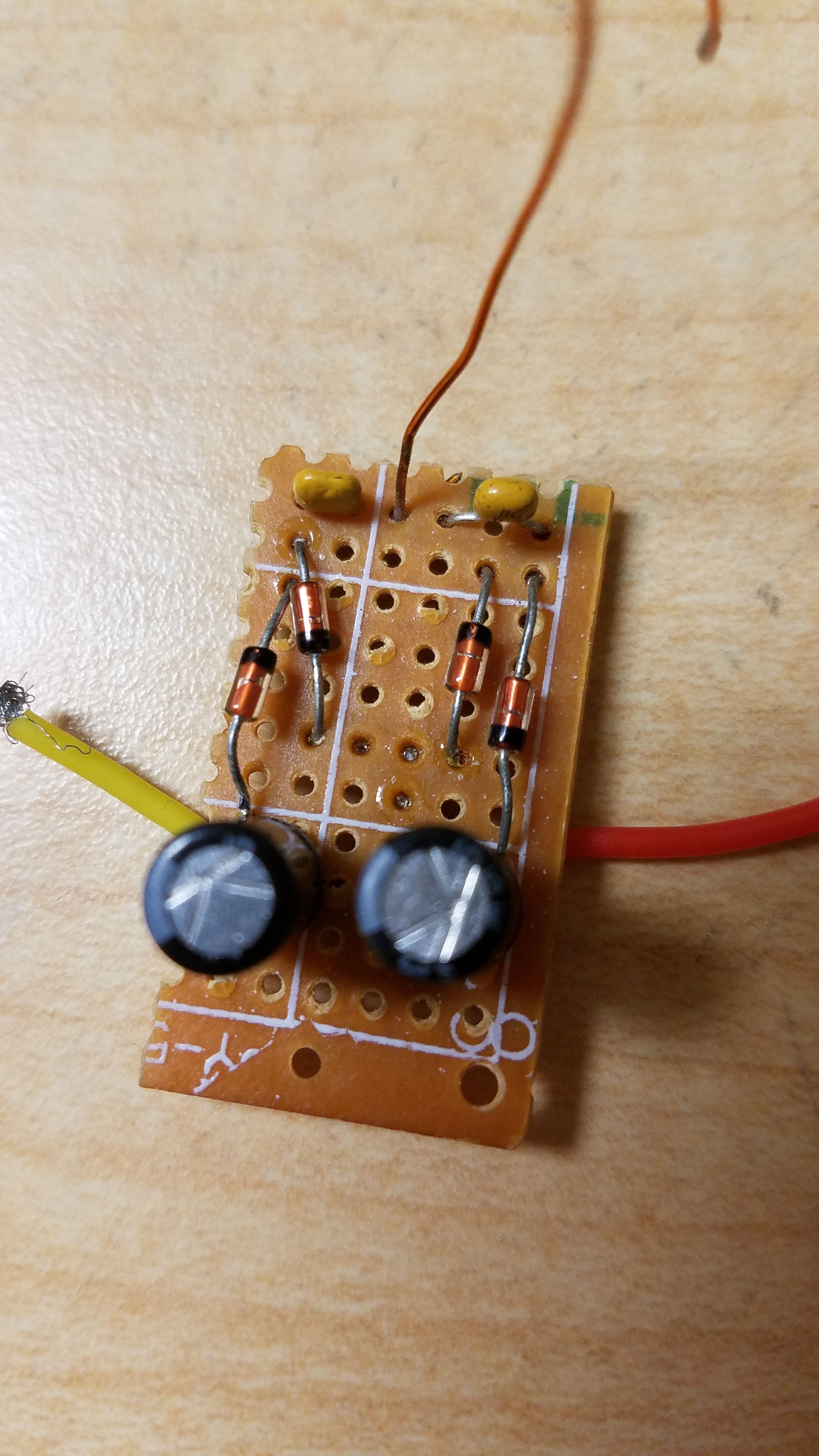
Here is a close-up shot of the final circuit. Yeah, I know it's ugly.

The red and yellow wires are just to make it easy for me to read the voltage on the storage capacitors - they are completely unnecessary.
I originally expected to get tiny (but detectable) energy generation, picked up on C3 and C4, just by leaving the circuit out in the room I built it in. When this didn't work, I thought it was broken. Turns out it wasn't: A ham radio transmitter confirmed that.
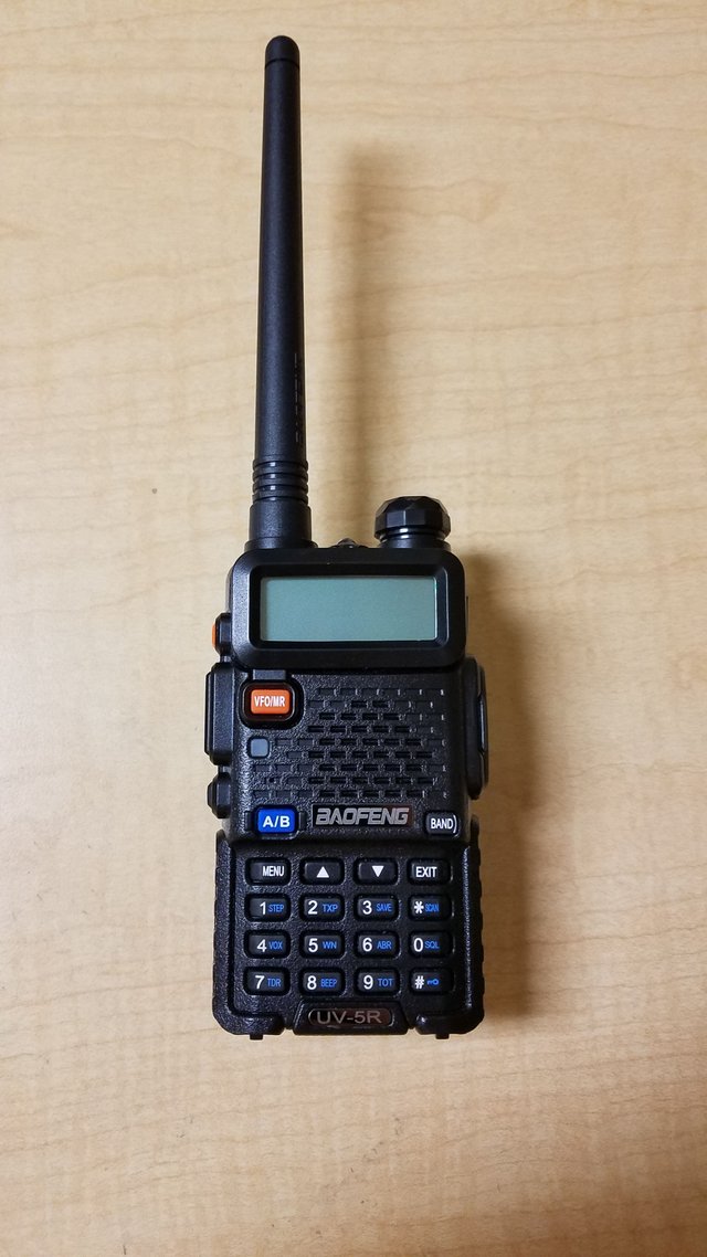
Using a Baofeng UV-5R handheld radio transmitter on the VHF band (~140 MHz) near the harvester causes the storage capacitor voltage to spike - so much so that I would be worried about them failing if the transmitter was left on for more than a few seconds. In a test I just did a couple minutes ago, quickly transmitting around 142 MHz (4W transmit power, nobody was using that frequency at the time) from a few inches away from the harvester caused the storage capacitors to quickly spike up to over 16 volts - not insignificant at all. This voltage was measured across the two electrolytic capacitors in series. In fact, this is easily enough to light an LED for a brief moment (or even break it, since LEDs are typically not rated for 16 volts).

My UV-5R transceiver. I used this handheld to test the harvester circuit above. If you're looking to get into ham radio, I highly recommend this device because it's very cheap (~$25), is somewhat sturdy, and offers UHF and VHF transmission/reception.
The UV-5R transmitter proves conclusively that the harvester is actually working ... somewhat. While you can harvest pretty decent amounts of energy an inch away from a four watt radio transmitter, this isn't useful outside of an experiment since ambient RF is nowhere near that energetic. Detecting ambient RF with this thing would be nice ...
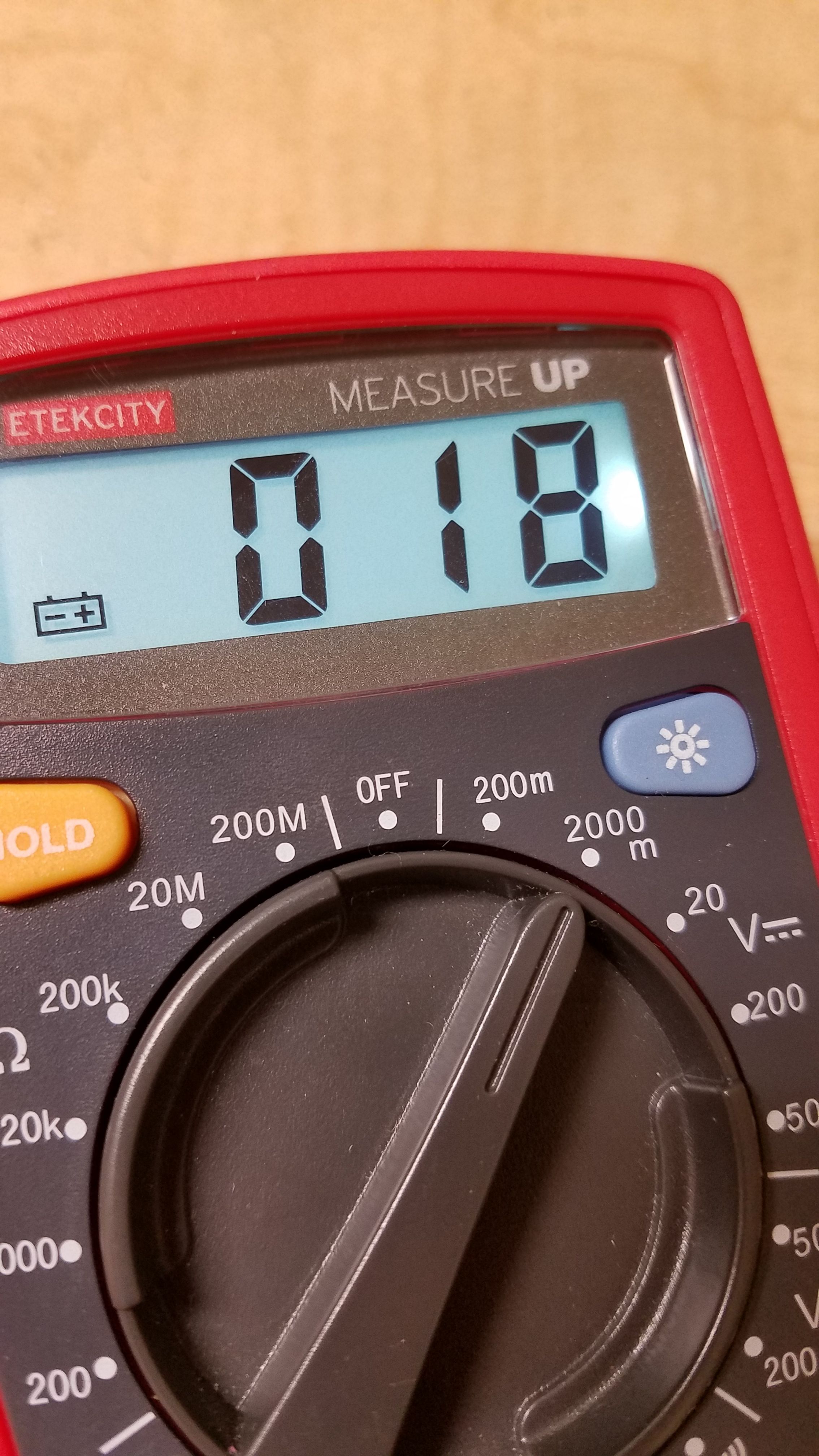
Well, I was able to do that too with this circuit. I just conducted another test where I shorted the storage capacitor and measured the storage capacitor voltage after 1 minute. The result: 18 millivolts. Here's the multimeter screen:

Various other informal tests returned similar results. For some reason, the circuit does actually harvest tiny amounts of energy from radio waves in my apartment but not in the room where I originally built the circuit. Not sure why there is more RF here, but whatever. The capacitors hooked up to the harvester charge themselves without external power source ... other than the radio waves transferring energy to the circuit, of course, to conserve energy.
Of course, 18 millivolts (that's 0.018 volts ... you should be laughing here) is pretty damn useless. But once again, this isn't exactly intended to be a useful product. There really isn't a lot of energy in ambient RF waves floating around to begin with. This just showed that the circuit works on both low and high levels of incident radio waves.
Conclusion
I don't personally see a practical use for this device. Ambient energy collection produces too low a capacitor voltage to be useful (although I may try some lower capacitance capacitors to see if I can get a higher voltage more quickly, which could then be potentially useful like my nuclear battery was). While you could technically produce okay amounts of energy by strapping this to the back of your ham radio and collecting whenever you talk, you are technically hindering your transmission range in the direction of the harvester by doing this - again, the energy has to come from somewhere, and if you are taking energy of out of the radio waves leaving the transmitter, those absorbed waves don't get to make it to the receiver of whoever you are calling. For this reason, putting such a harvester on, say, your cell phone, would just make it more difficult to receive calls from cell towers in the direction of the harvester, since the harvester is essentially providing partial shielding by absorbing some of the RF emissions.
If there was a way to produce practical voltages from ambient RF using this, then I could see this being useful (even if just as a gimmick). This is of course totally possible, and electronics manufacturers have already built circuits that can do this. It's just a lot harder with DIY tools, big components, and only minimal understanding of RF antenna theory. But I'll probably keep trying and keep you posted if I have any luck.
I hope you learned something from this project! If you have any questions, comments, corrections, or rants, feel free to let me know. I hope to eventually improve this device a bit, so let me know if you have any suggestions for improvement!
Thanks for reading!
Images not credited are my own. You are welcome to use them in your own posts with credit.

Downvoting a post can decrease pending rewards and make it less visible. Common reasons:
Submit
I recently read about a company that is transferring power via waves between 1-5m. There must be some wave range where this works quite well then. Dont remeber where it was.
Downvoting a post can decrease pending rewards and make it less visible. Common reasons:
Submit
Wireless power definitely works, but it's usually pretty inefficient. After writing this I had the idea of using this harvester as an RF detector by adding an LED that lights up when it gets close to something transmitting by using energy in the storage capacitors. This would let you detect stuff like FM transmitters without seeing them. I'm going to try to throw it together and make a post in a few days about it if you're interested.
Downvoting a post can decrease pending rewards and make it less visible. Common reasons:
Submit