Last time I bought couple of accessories for my Raspberry Pi3 from the bookstore in Shamshuipo.
上次在深水埗那書店買了幾件配件給我的樹莓派。
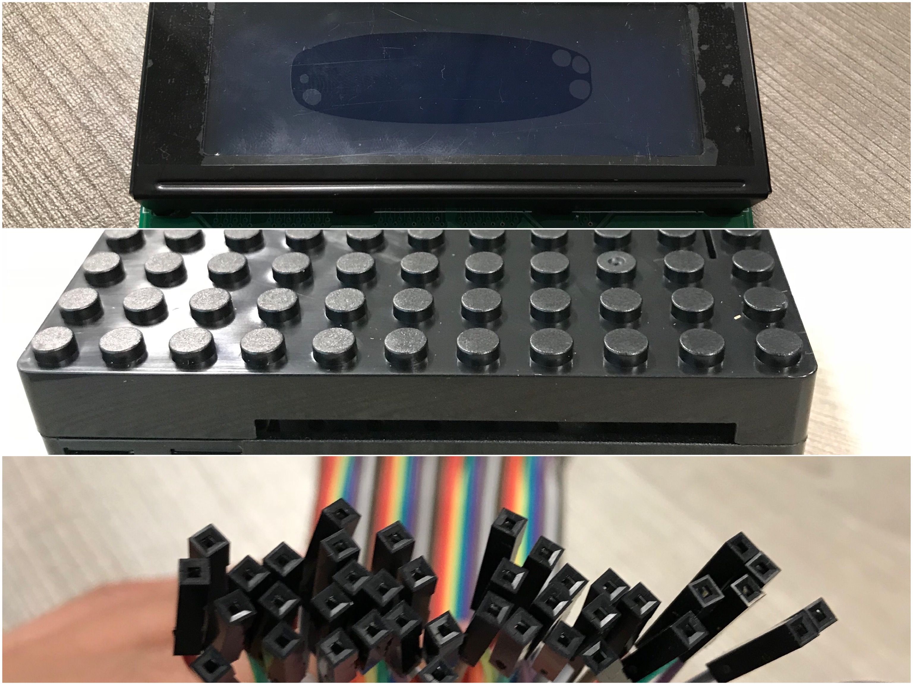
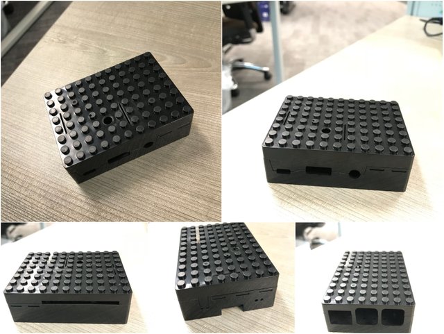
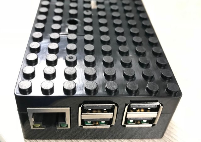
Let see what they are: First came a Lego-style box for Raspberry Pi3, look at the openings, they were customized for Pi 3.
讓我們仔細看看:先來是樂高積木款式的盒子,看看那些口子就知道這是pi 3 專用的。
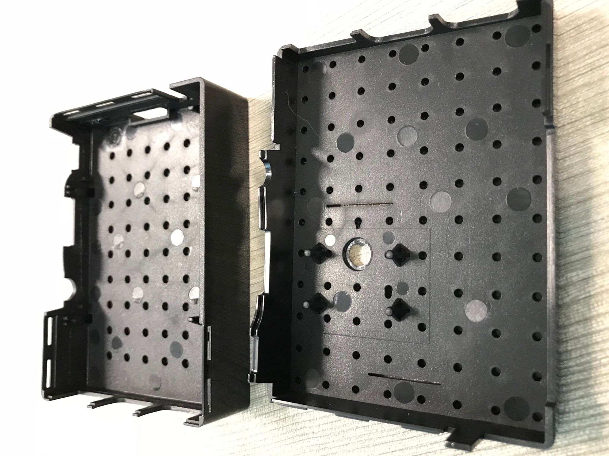
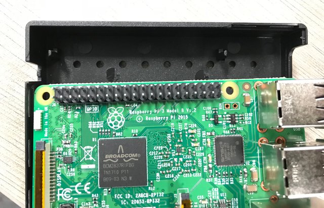
Just need to align the holes on circuit board with the poles on the case, it was fairly easy to put Pi 3 in the case. This was how it looks like afterward.
只需要將電路板上的小孔對準盒中的小棒子,就可以把樹莓派安裝到盒子中。完成後就是這個樣子。
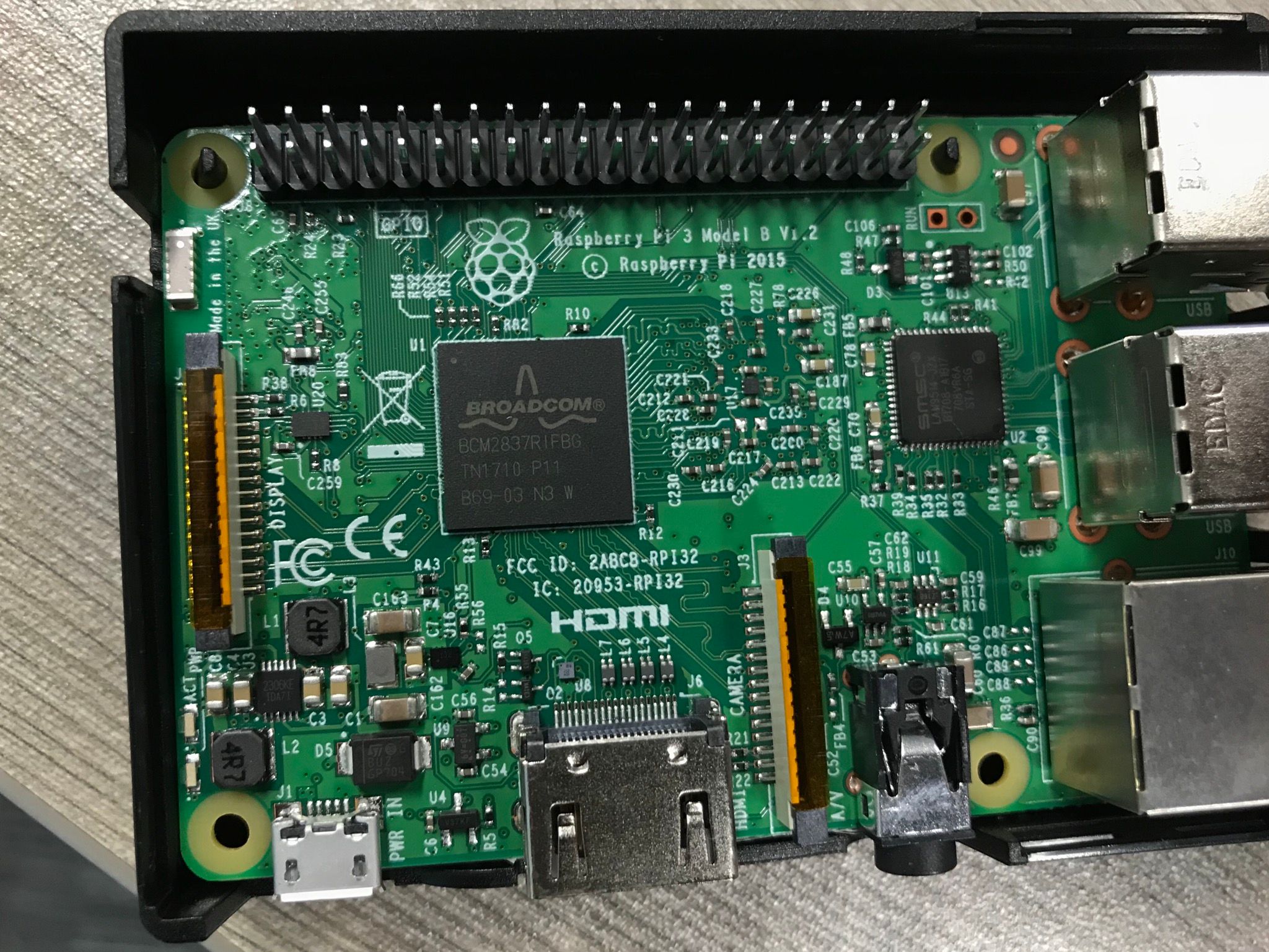
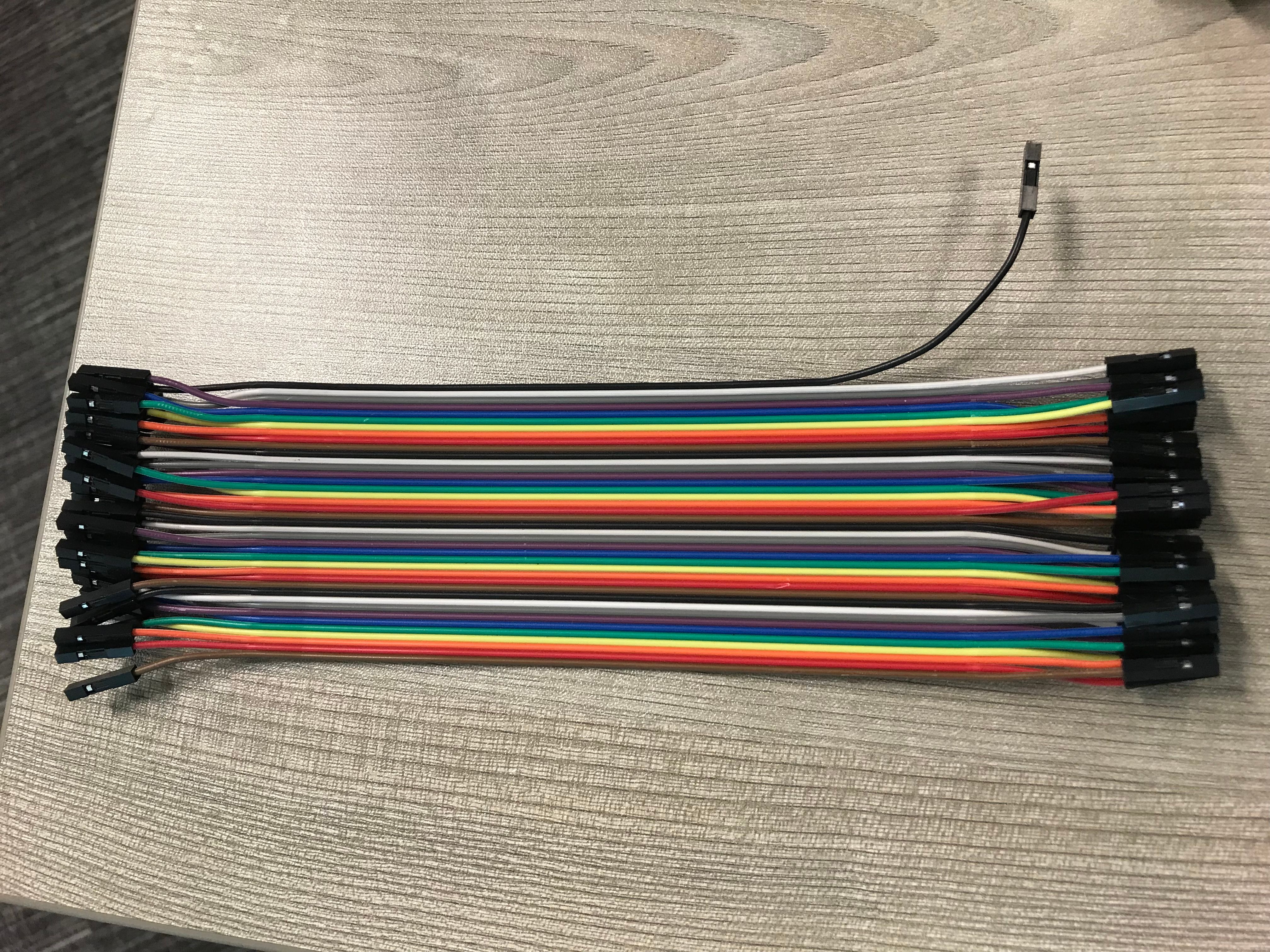
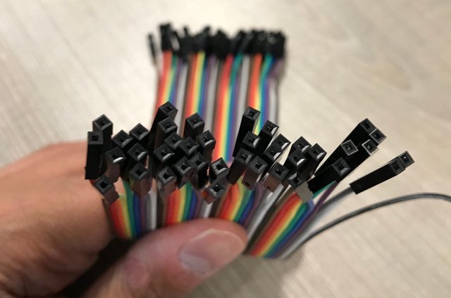
The other 2 accessories were one integrated 20x4 LCD display and some female-to-female breadboard cables.
另外兩件配件是一塊經已整合好的20x4液晶顯示板和一些麵包板連接線。
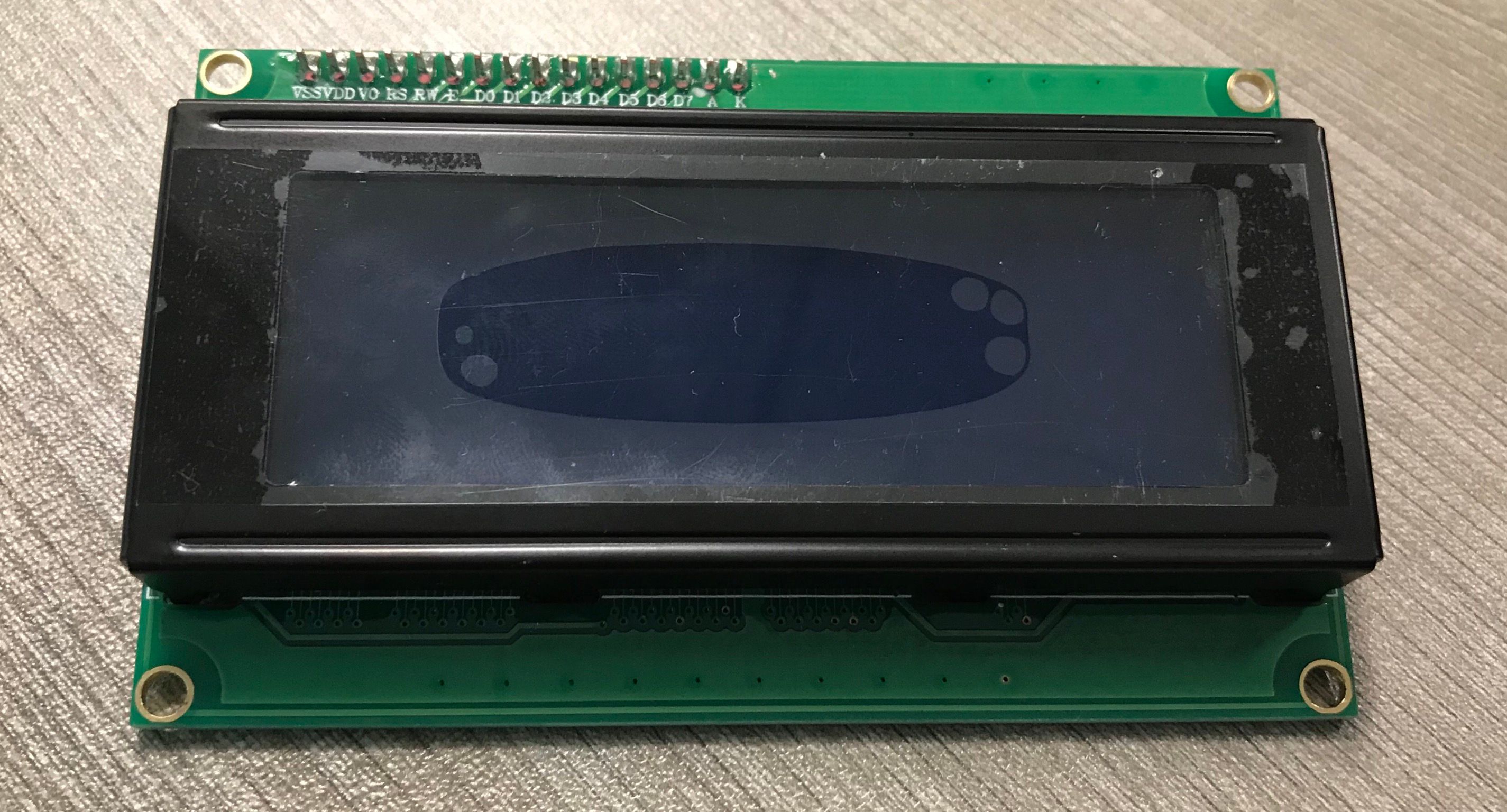
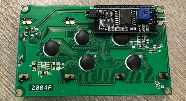
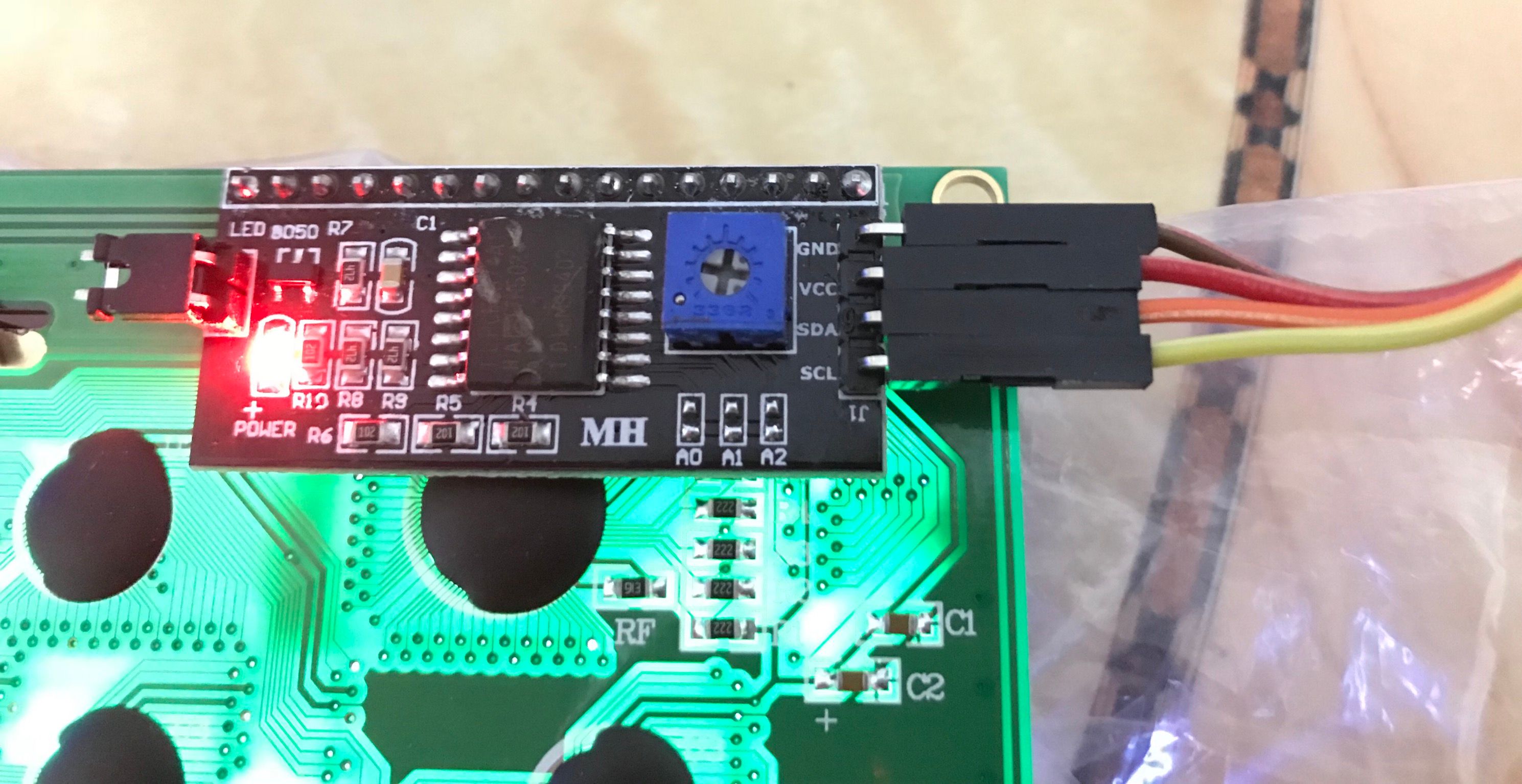
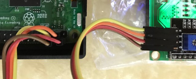
I was going to connect this LCD to Pi3 and use it for displaying of text. First of all I had to connect it to Pi3. The LCD already has a I2C LCD Controller integrated, I only need to connect the 4 pins of the controller to the GPIO pins of Pi3 using following mapping :
| LCD Pin # | Pi3 GPIO Pin # |
|---|---|
| GND | PIN 6 |
| VCC | PIN 2 |
| SDA | PIN 3 |
| SCL | PIN 5 |
我想把液晶顯示板接到樹莓派上作為顯示之用。所以我因為液晶顯示板已經整合了控制器,所以我只需根據上面的針腳配置表將它接到樹莓派的GPIO針腳上。
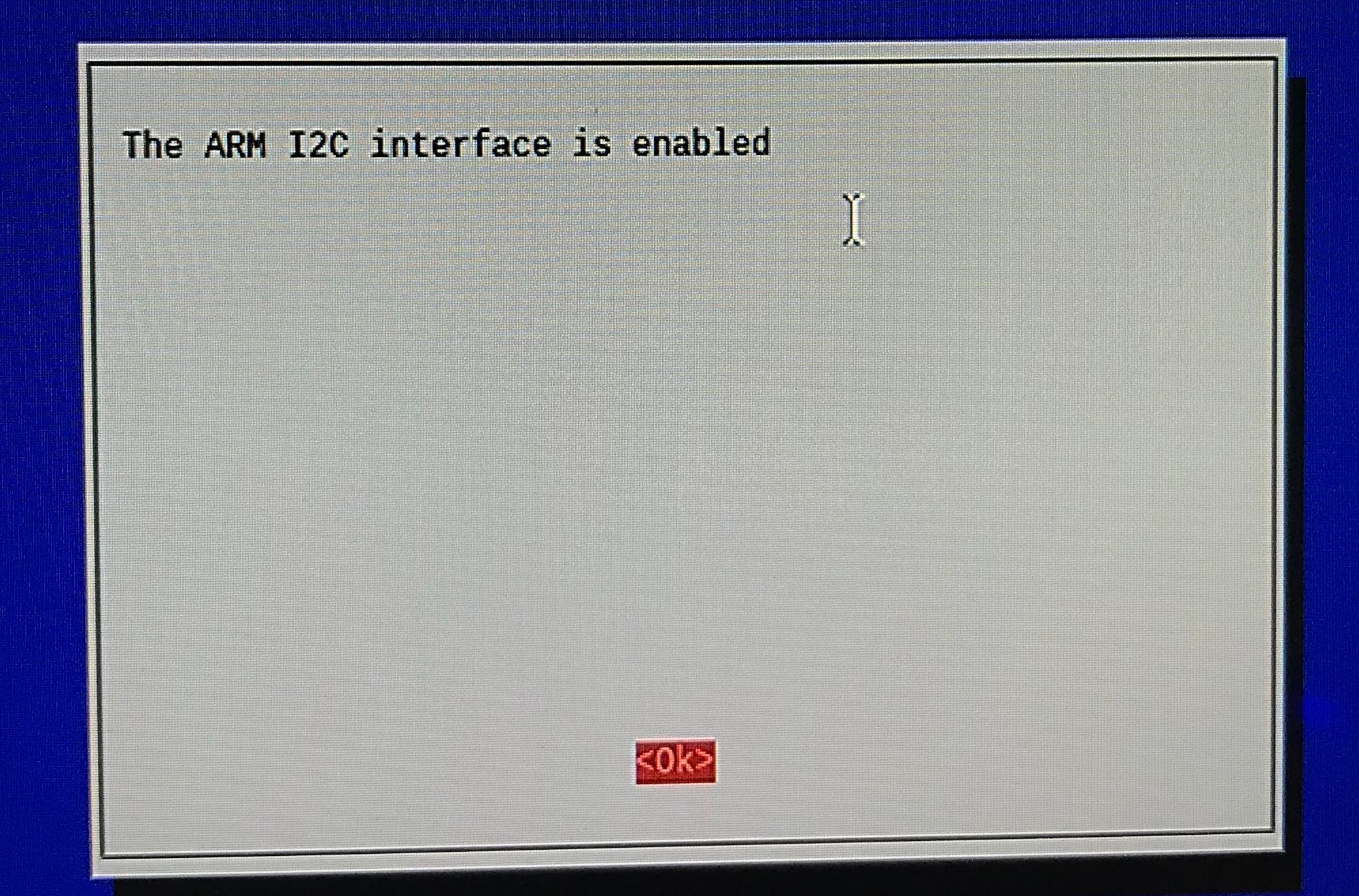
Then I had to enable i2c on Pi3. From Command Line type : sudo raspi-config
先要開啟在樹莓派上的i2c 支援,在命令行鍵入上面的命令
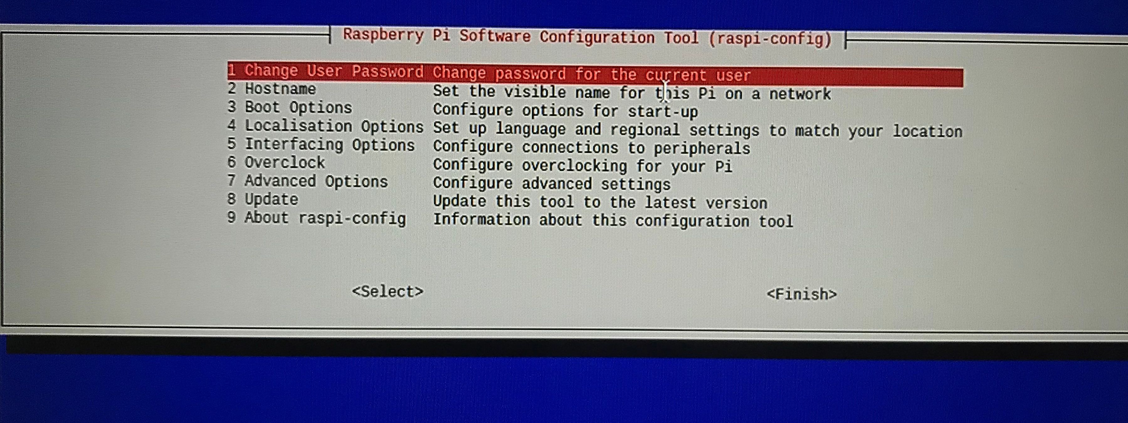
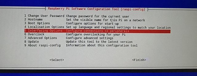
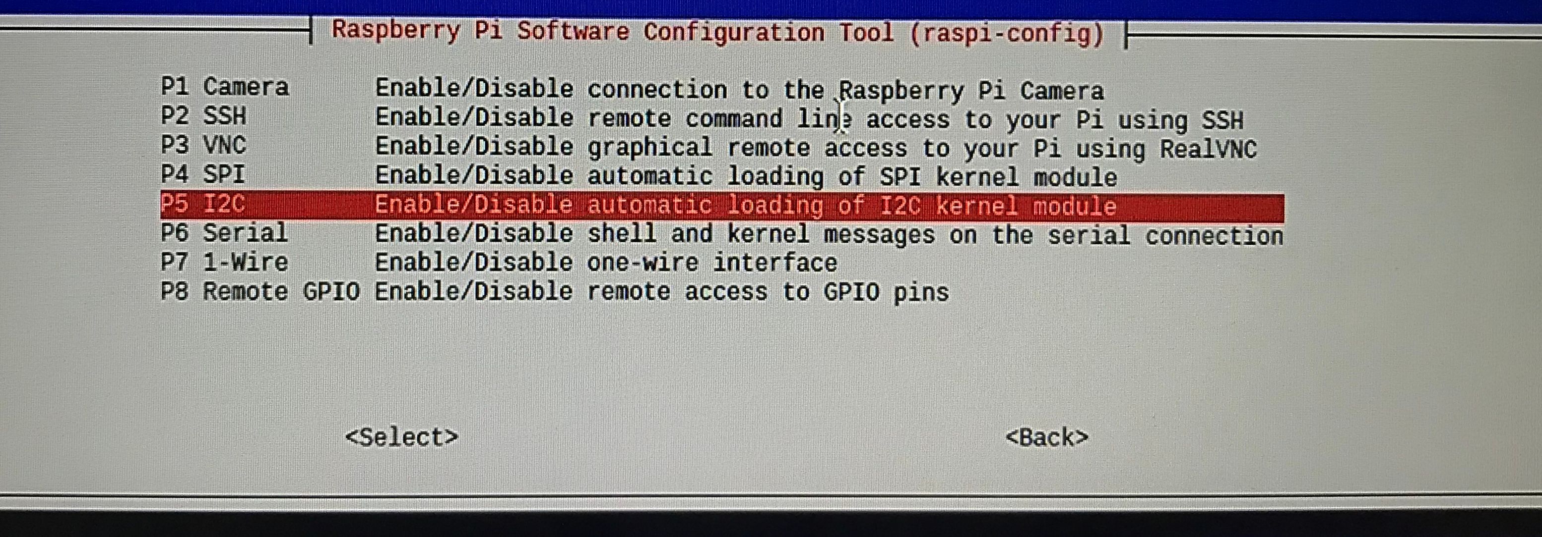
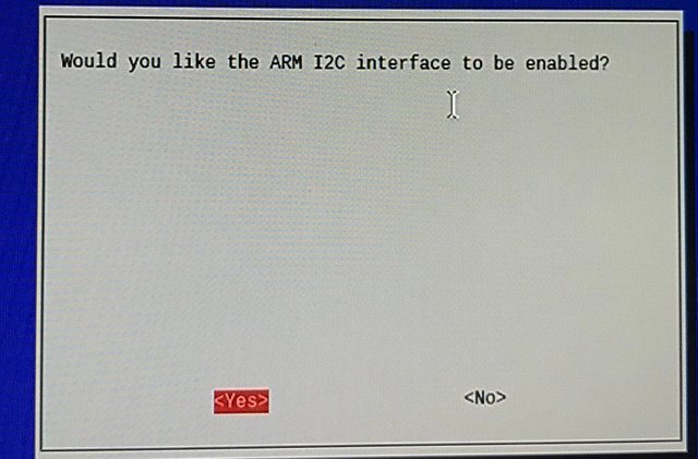
Complete following steps:
- Select "Interfacing Options"
- Select "I2C"
- Select "Yes"
- Select "Ok"
Then select "Finish" to quit raspi-config.
完成上面的步驟之後就選"Finish"去離開。
Then I have to install python i2c utilities "python-smbus" & "i2c-tools" by typing following commands in Command Line:
- sudo apt-get update
- sudo apt-get install -y python-smbus i2c-tools
在命令行打入上面的命令去安裝 python 應用 "python-smbus" 和 "i2c-tools"。
I tested the LCD hardware by
- sudo i2cdetect -y 1
利用上面的命令去測驗液晶顯示板
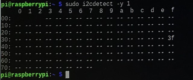
This showed the LCD was connected to address 0x3f.
可以見到液晶顯示板已經連接到記憶地址0x3f。
In order to talk to the LCD, python libraries were needed. Using following to steps to create the libraries:
要用上液晶顯示板,先要有相對應的python代碼庫。利用下面的命令去建立兩個檔案:
- sudo nano i2c_lib.py
type following in the file:
把下面的代碼輸入到檔案中:
import smbus
from time import *

class i2c_device:
   def __init__(self, addr, port=1):
      self.addr = addr
      self.bus = smbus.SMBus(port)

# Write a single command
   def write_cmd(self, cmd):
      self.bus.write_byte(self.addr, cmd)
      sleep(0.0001)

# Write a command and argument
   def write_cmd_arg(self, cmd, data):
      self.bus.write_byte_data(self.addr, cmd, data)
      sleep(0.0001)

# Write a block of data
   def write_block_data(self, cmd, data):
      self.bus.write_block_data(self.addr, cmd, data)
      sleep(0.0001)

# Read a single byte
   def read(self):
      return self.bus.read_byte(self.addr)

# Read
   def read_data(self, cmd):
      return self.bus.read_byte_data(self.addr, cmd)

# Read a block of data
   def read_block_data(self, cmd):
      return self.bus.read_block_data(self.addr, cmd)
And other file | 第二個檔案:
- sudo nano lcddriver.py
Type following in the file:
把下面的代碼輸入到檔案中:
import i2c_lib
from time import *

# LCD Address
ADDRESS = 0x3f

# commands
LCD_CLEARDISPLAY = 0x01
LCD_RETURNHOME = 0x02
LCD_ENTRYMODESET = 0x04
LCD_DISPLAYCONTROL = 0x08
LCD_CURSORSHIFT = 0x10
LCD_FUNCTIONSET = 0x20
LCD_SETCGRAMADDR = 0x40
LCD_SETDDRAMADDR = 0x80

# flags for display entry mode
LCD_ENTRYRIGHT = 0x00
LCD_ENTRYLEFT = 0x02
LCD_ENTRYSHIFTINCREMENT = 0x01
LCD_ENTRYSHIFTDECREMENT = 0x00

# flags for display on/off control
LCD_DISPLAYON = 0x04
LCD_DISPLAYOFF = 0x00
LCD_CURSORON = 0x02
LCD_CURSOROFF = 0x00
LCD_BLINKON = 0x01
LCD_BLINKOFF = 0x00

# flags for display/cursor shift
LCD_DISPLAYMOVE = 0x08
LCD_CURSORMOVE = 0x00
LCD_MOVERIGHT = 0x04
LCD_MOVELEFT = 0x00

# flags for function set
LCD_8BITMODE = 0x10
LCD_4BITMODE = 0x00
LCD_2LINE = 0x08
LCD_1LINE = 0x00
LCD_5x10DOTS = 0x04
LCD_5x8DOTS = 0x00

# flags for backlight control
LCD_BACKLIGHT = 0x08
LCD_NOBACKLIGHT = 0x00

En = 0b00000100 # Enable bit
Rw = 0b00000010 # Read/Write bit
Rs = 0b00000001 # Register select bit

class lcd:
   #initializes objects and lcd
   def __init__(self):
      self.lcd_device = i2c_lib.i2c_device(ADDRESS)

      self.lcd_write(0x03)
      self.lcd_write(0x03)
      self.lcd_write(0x03)
      self.lcd_write(0x02)

      self.lcd_write(LCD_FUNCTIONSET | LCD_2LINE | LCD_5x8DOTS | LCD_4BITMODE)
      self.lcd_write(LCD_DISPLAYCONTROL | LCD_DISPLAYON)
      self.lcd_write(LCD_CLEARDISPLAY)
      self.lcd_write(LCD_ENTRYMODESET | LCD_ENTRYLEFT)
      sleep(0.2)

   # clocks EN to latch command
   def lcd_strobe(self, data):
      self.lcd_device.write_cmd(data | En | LCD_BACKLIGHT)
      sleep(.0005)
      self.lcd_device.write_cmd(((data & ~En) | LCD_BACKLIGHT))
      sleep(.0001)

   def lcd_write_four_bits(self, data):
      self.lcd_device.write_cmd(data | LCD_BACKLIGHT)
      self.lcd_strobe(data)

   # write a command to lcd
   def lcd_write(self, cmd, mode=0):
      self.lcd_write_four_bits(mode | (cmd & 0xF0))
      self.lcd_write_four_bits(mode | ((cmd << 4) & 0xF0))

   # put string function
   def lcd_display_string(self, string, line):
      if line == 1:
         self.lcd_write(0x80)
      if line == 2:
         self.lcd_write(0xC0)
      if line == 3:
         self.lcd_write(0x94)
      if line == 4:
         self.lcd_write(0xD4)

      for char in string:
         self.lcd_write(ord(char), Rs)

   # clear lcd and set to home
   def lcd_clear(self):
      self.lcd_write(LCD_CLEARDISPLAY)
      self.lcd_write(LCD_RETURNHOME)
Make sure the i2C address in this file is set to #3f.
記得要把代碼中的i2c地址改成 #3f.
# LCD Address
ADDRESS = 0x3f
Finally I could use the LCD dispaly by creating a python script file:
最後就是建立python檔案來顯示文字到液晶顯示板:
- sudo nano display.py
# loading the class
import lcddriver

from time import *

import time

# lcd start
lcd = lcddriver.lcd()

# this command clears the display (captain obvious)
lcd.lcd_clear()
# clock = time()

actions = ['Follow', ' Vote', ' Resteem']
action1 = ""
print ("Start : %s" % time.ctime())

# now we can display some characters (text, line)
lcd.lcd_display_string("Hello Steemit !", 1)
lcd.lcd_display_string("This is @guyverckw", 2)
lcd.lcd_display_string("   Please   ", 3)
for action in actions :
        action1 = action1 + action
        lcd.lcd_display_string(action1 , 4)
        time.sleep( 2 )

print ("End : %s" % time.ctime())
Then run the script | 執行代碼:
- python display.py
Then you should able to see this:
應該就能見到這樣:

I encountered a major problem when trying to make this works, there was nothing displayed on the LCD. After checking a lot of works from others, I found that it was the contrast of the LCD was not properly set. Contrast of it can be set at the switch on the controller:
我在這個過程中遇到最大的問題就是在液晶顯示板上看不見任何東西。經過大量翻查其他人的經驗,我發現原來是因為液晶顯示板的對比度設置得不好。只要在控制器上的這個開關上扭動一下,就可以改變對比度。
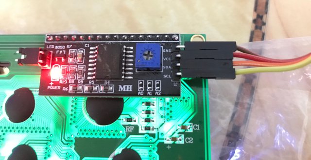
After contrast was adjusted correctly texts could be seen on LCD.
對比度設置妥當就能見到文字了。
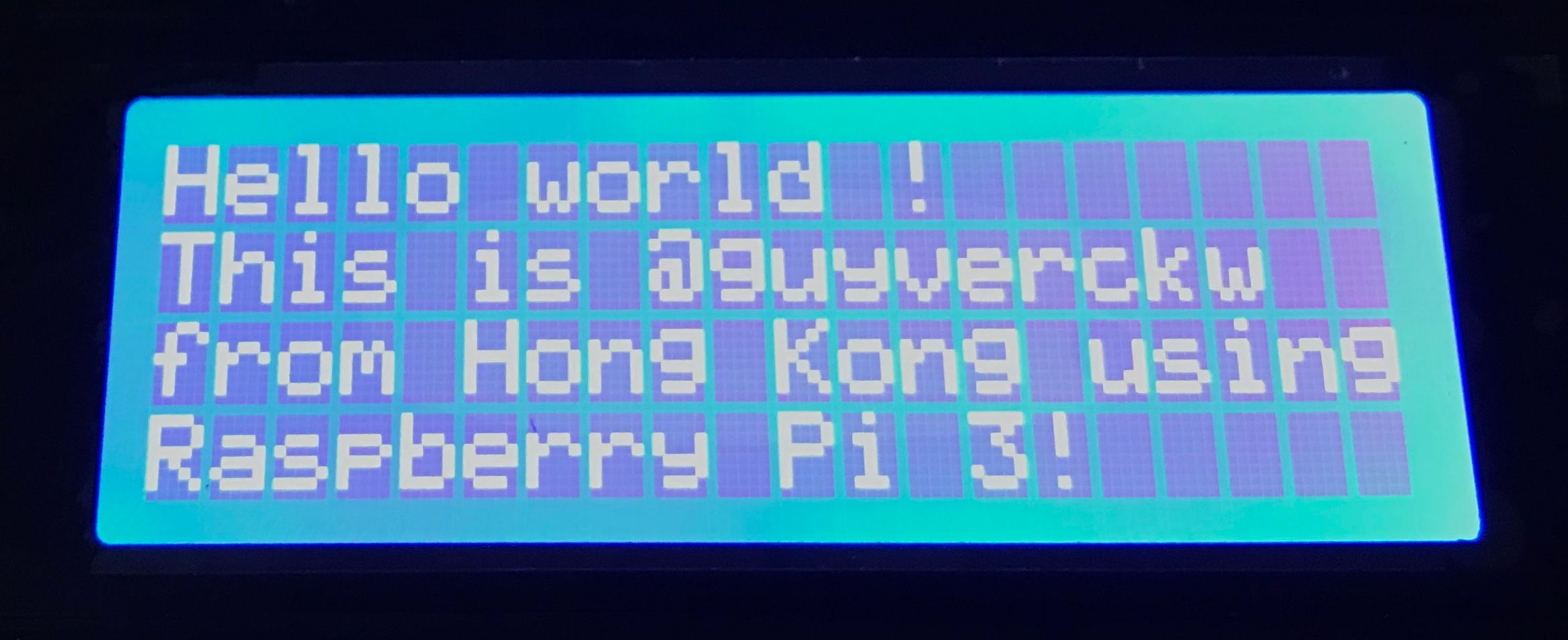
This conclude my test with this 20x4 LCD panel. I will use it on other projects later. I will share them after they are done. Stay tuned.
液晶顯示板的初試驗完滿結束。我將會把它用於其他的項目上面。有機會再為大家分享。
請關注!點讚!轉發!

Please Follow! Upvote! Resteem!
兼賣樹莓派的書店 | Bookstore that sold Raspberry Pi parts
樹莓派 3 開盒及初建分享 | Raspberry Pi 3 Open box and Setup
!steemitworldmap 22.331800 lat 114.161748 long d3scr
wow this really requires a lot of skill I do not think I can build this on my own.
Downvoting a post can decrease pending rewards and make it less visible. Common reasons:
Submit
Frankly, follow exactly the steps in my post, it is not difficult to build the same thing. Give it a try.
Downvoting a post can decrease pending rewards and make it less visible. Common reasons:
Submit
Upped!! Will you soon try SteemPi on it ? :)
Downvoting a post can decrease pending rewards and make it less visible. Common reasons:
Submit
Actually, SteemPi is now on it already, just the LED part I not yet tested. After the LED part is done, I will post it.
Downvoting a post can decrease pending rewards and make it less visible. Common reasons:
Submit
Awesome :)
I just bought steempi.com (you can see it in my latest post very happy :) ! )
Downvoting a post can decrease pending rewards and make it less visible. Common reasons:
Submit
This is a test for the LED notification of Steempi.
Downvoting a post can decrease pending rewards and make it less visible. Common reasons:
Submit
That's looks a great buy :D
Downvoting a post can decrease pending rewards and make it less visible. Common reasons:
Submit
Yes, it is fun.
Downvoting a post can decrease pending rewards and make it less visible. Common reasons:
Submit
说难不难,说简单也不简单的小玩具啊。
Downvoting a post can decrease pending rewards and make it less visible. Common reasons:
Submit
太容易就真的變成玩具了
Downvoting a post can decrease pending rewards and make it less visible. Common reasons:
Submit
好繽紛的線! 希望之後可以看見你們都玩些什麼~ :D
Downvoting a post can decrease pending rewards and make it less visible. Common reasons:
Submit
Yes, madam!
Downvoting a post can decrease pending rewards and make it less visible. Common reasons:
Submit
Nice!!! :D
Downvoting a post can decrease pending rewards and make it less visible. Common reasons:
Submit
like your post....
Downvoting a post can decrease pending rewards and make it less visible. Common reasons:
Submit
雖然完全看不明白,但是用那 Lego 組裝很有趣!👍🏻👍🏻
Downvoting a post can decrease pending rewards and make it less visible. Common reasons:
Submit
找不到其他Lego配件,否則應該更有趣
Downvoting a post can decrease pending rewards and make it less visible. Common reasons:
Submit
are you a engineer
Downvoting a post can decrease pending rewards and make it less visible. Common reasons:
Submit
I used to be, not anymore
Downvoting a post can decrease pending rewards and make it less visible. Common reasons:
Submit
Wow nice post
Downvoting a post can decrease pending rewards and make it less visible. Common reasons:
Submit
Very good man
Downvoting a post can decrease pending rewards and make it less visible. Common reasons:
Submit
Thanks for sharing..
Downvoting a post can decrease pending rewards and make it less visible. Common reasons:
Submit
Nice buy.
Downvoting a post can decrease pending rewards and make it less visible. Common reasons:
Submit